Diving slamming experimentation device for ocean structure

A technology for marine structures and experimental devices, which is applied to measurement devices, machine/structural component testing, impact testing, etc., can solve the problems of a single working mode of the load-throwing mechanism, increase the experimental cost, etc., and achieve good practicability and market value. , easy to create and operate, easy-to-control effects

Active Publication Date: 2015-06-10
HARBIN ENG UNIV
View PDF8 Cites 28 Cited by
  • Summary
  • Abstract
  • Description
  • Claims
  • Application Information

AI Technical Summary

Problems solved by technology

In the past, the dumping mechanism often only had a single working mode, which greatly increased the cost of the experiment

Method used


Image

  • Diving slamming experimentation device for ocean structure
  • Diving slamming experimentation device for ocean structure
  • Diving slamming experimentation device for ocean structure

Examples


Embodiment example 1

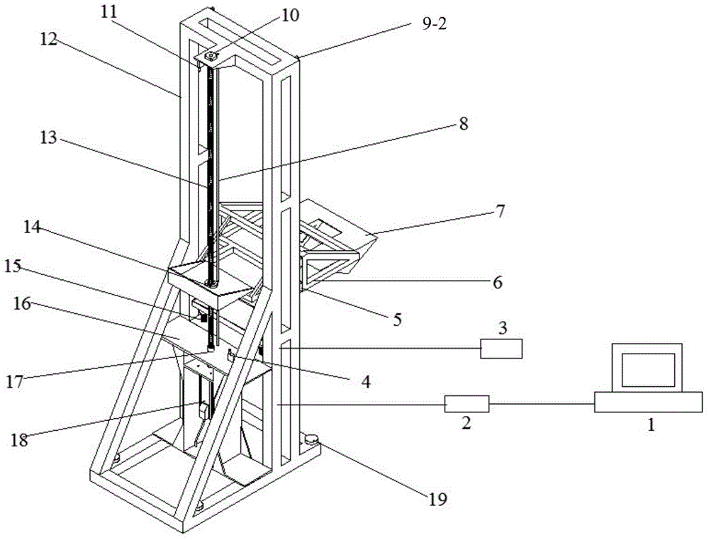
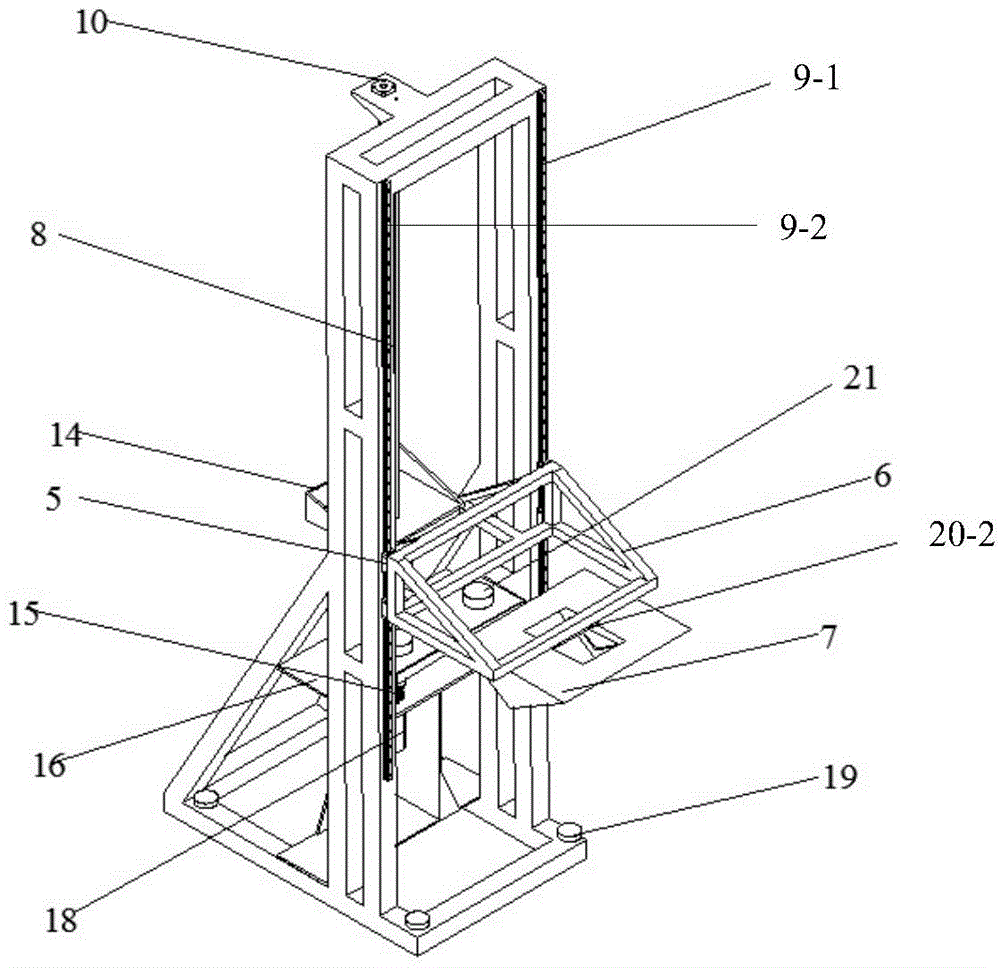
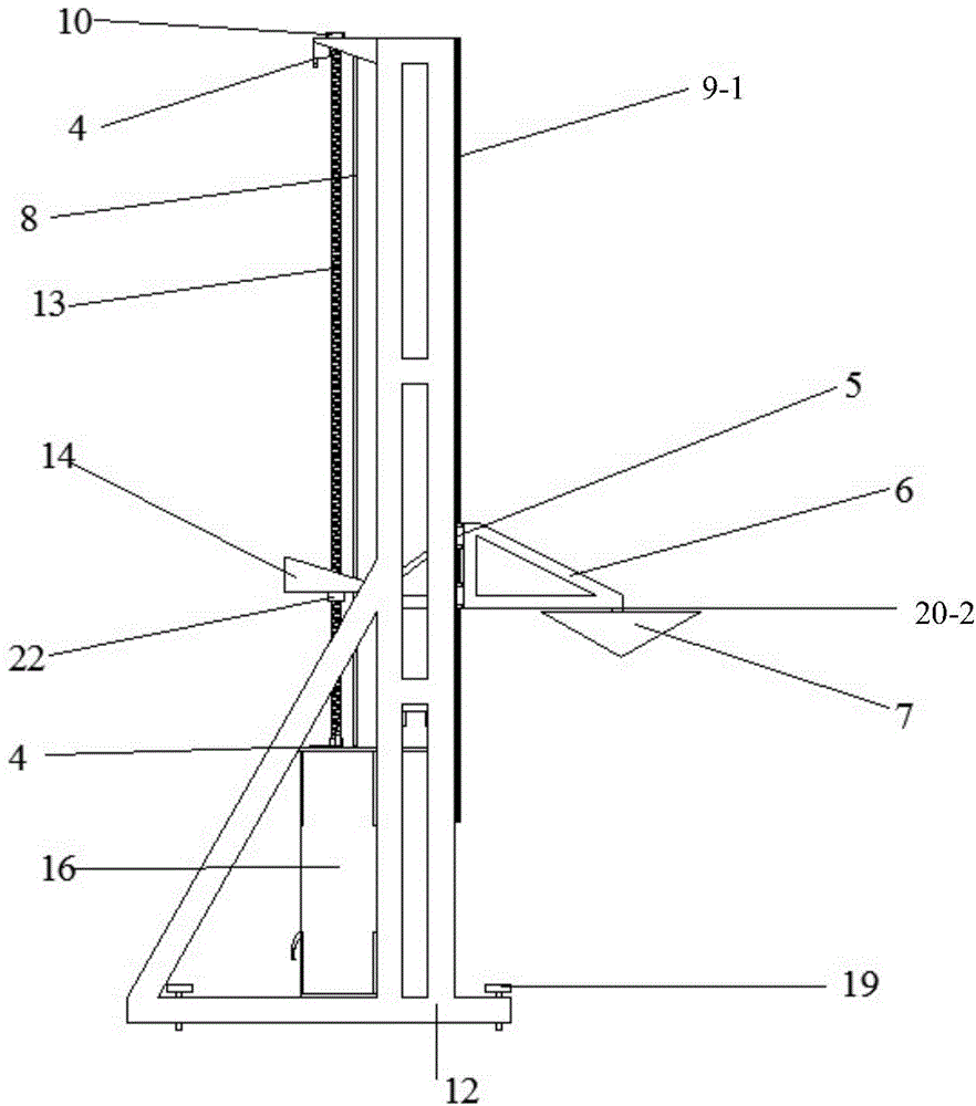
[0019] Implementation Case 1: Combining Figure 1 to Figure 3 , Figure 5 to Figure 8 , the present invention includes a base 12, a structure 7, a motor base 16 installed in the middle of the base 12, a motor 18 installed at the lower end of the motor base 16, a lead screw 13 connected to the output shaft of the motor 18, and a screw 13 sleeved on the wire The first-level throwing slide frame 14 on the bar 13, two vertical guide rails 9-1 and 9-2 installed on both sides of the base 12, symmetrically installed on the two vertical guide rails 9-1 and 9-2 Four slide blocks 5 and the secondary dumping slide frame 6 that are fixedly installed on the four slide blocks 5, the said primary dumping slide frame 14 is sleeved on the lead screw 13 means that the primary dumping slide frame 14 is set by The lead screw nut 22 is sleeved on the lead screw 13, the first electromagnet 20-1 is arranged on the first-stage dumping carriage 14, the second electromagnet 20-2 is arranged on the sec...

Embodiment example 2

[0020] Implementation Case 2: Based on the above-mentioned embodiment combined with Figure 4 , the present invention can also be: also include a buffer system, the buffer system includes a buffer base 24, a spring shock absorber 15, a buffer platform 23 and a rubber block 21, wherein the buffer base 24 is welded to the vertical frame of the base 12 In 31, it is flat with the top plate of the motor base 16, and the spring shock absorber 15 is installed on the buffer base 24, which is connected with the buffer platform 23, and the rubber block 21 is bonded to the buffer platform 23 by resin, That is to say, a buffer base 24 is also installed on the base 12, and the buffer base 24 and the motor base 16 are symmetrically located at the same horizontal position at the two ends of the base 12, and the four corners of the buffer base 24 are respectively Spring shock absorbers 15 are provided, and buffer platforms 23 are installed on the upper surfaces of the four spring shock absorb...


PUM


Abstract

The invention discloses a diving slamming experimentation device for an ocean structure. The diving slamming experimentation device for the ocean structure comprises the structure, a power system, a load rejection system, a control and measurement system, a buffer system and a substrate, the power system mainly comprises a motor seat, a screw rod, a vertical lead rail, an optical axis and a screw rod; the load rejection system comprises a primary load rejection carriage, a secondary load rejection carriage, an electromagnet and a slide block; the control and measurement system mainly comprises a computer, a data gatherer, a constant-voltage direct current power supply, and an upper and a lower limit switch, the buffer system comprises a buffer substrate, a spring bumper and a buffer platform, the control and measurement system controls through motor motion and magnetic force of the electromagnet to realize primary load rejection and secondary load rejection, the structure falls into the water, and a pressure sensor arranged on the structure returns the measured data to the computer through the data gatherer. The diving slamming experimentation device for the ocean structure is simple in structure, convenient to operate, stable in move and suitable for the diving slamming experiments for different types of ocean structures.

Description

technical field [0001] The invention relates to the field of ship and marine engineering experiments, in particular to a device for slamming a marine structure into water. Background technique [0002] The water landing of seaplanes and spaceships, the water impact of air-dropped torpedoes, the slamming of ships in wind and waves, and the throwing of lifeboats at sea will arouse the movement of the surrounding fluid medium; in turn, the fluid medium exerts pressure on the structure Various reaction forces, especially in the initial transient period (milliseconds) of the impact of entering the water, will suffer a huge impact load. This involves the dynamics of structural man-water impact. The research on the human-water problem plays an important role in the design of the strength of the water-entry structure: for example, in the process of air-dropped or rocket-assisted underwater weapons invading from the air medium to the fluid medium, they are faced with structural damag...

Claims


Application Information

Patent Timeline
Patent Type & Authority Applications(China)
IPC IPC(8): G01M7/08
Inventor 段文洋陈云赛金善勤黄礼敏韩阳郑兴赵彬彬
Owner HARBIN ENG UNIV
Why Eureka
Try Eureka