Magnetic-coupling cold testing device for dumbbell-shaped resonant cavity

A technology of magnetic coupling and resonant cavity, which is applied in the field of magnetic coupling method cold measurement device of dumbbell-shaped resonant cavity, can solve the problems of numerical reduction, slow response speed, difficult actual structure, etc., and achieve the effect of eliminating confusion

Inactive Publication Date: 2015-06-10
INST OF ELECTRONICS CHINESE ACAD OF SCI
View PDF5 Cites 0 Cited by
  • Summary
  • Abstract
  • Description
  • Claims
  • Application Information

AI Technical Summary

Problems solved by technology

[0005] The main technical defect: due to the special structure of the dumbbell-shaped resonator, the thickness of the straight waveguide in the middle (along the direction of electron beam movement, z-axis) and the height of the drift channel (narrow side direction, y-axis) are relatively small, and, As the operating frequency increases, its value will further decrease. Therefore, in the millimeter wave band (such as the W wave band), according to the Argonne National Laboratory in the United States, the method of opening a hole on the end face of the middle straight waveguide to place a small current loop In the actual structure will face great difficulties
[0006] Minor technical defects: Experiments show that the response speed of existing network analyzers is slow, and the measured S-parameter curve cannot quickly respond to external disturbances or changes in external excitations
Due to the large number of modes in the dumbbell-shaped cavity, it is necessary to discriminate them by perturbing them according to the field distribution characteristics of the working mode, although the performance of the network analyzer will be greatly improved with the advancement of technology in the future , but currently due to its slow response speed, this will cause difficulty in mode confirmation

Method used


Image

  • Magnetic-coupling cold testing device for dumbbell-shaped resonant cavity
  • Magnetic-coupling cold testing device for dumbbell-shaped resonant cavity
  • Magnetic-coupling cold testing device for dumbbell-shaped resonant cavity

Examples


Embodiment Construction

[0031] In order to make the object, technical solution and advantages of the present invention clearer, the present invention will be further described in detail below in conjunction with specific embodiments and with reference to the accompanying drawings.

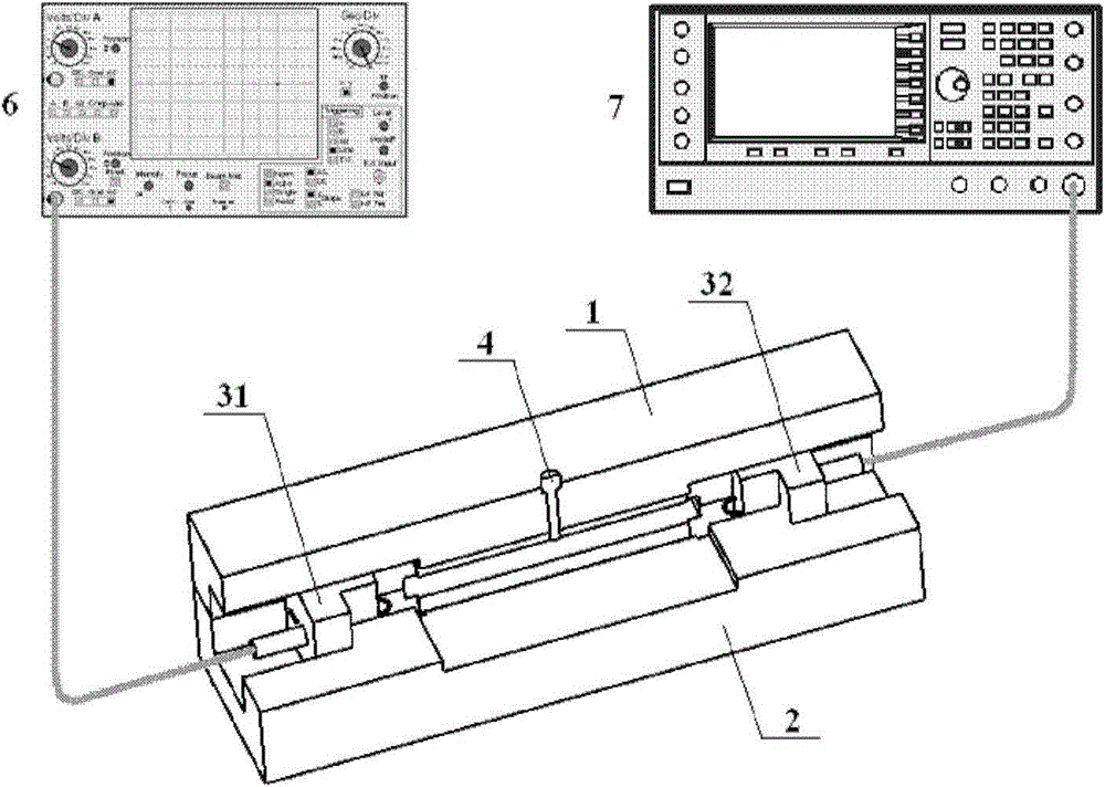
[0032] figure 2 A cross-sectional structure diagram of a magnetic coupling method cold measuring device for a dumbbell-shaped resonant cavity proposed by the present invention is shown. like figure 2 As shown, the device includes an upper cover plate 1, a lower cover plate 2, a first magnetic coupling block 31, a second magnetic coupling block 32, a perturbation rod 4 and a sealing round nail 5 ( figure 2 not shown in). Wherein, the structure of the upper cover plate 1 and the lower cover plate 2 is basically the same, and after the upper cover plate 1 and the lower cover plate 2 are put together, a dumbbell-shaped single-gap resonant cavity and the dumbbell-shaped single-gap resonant cavity are formed between the tw...


PUM


Abstract

The invention discloses a magnetic-coupling cold testing device for a dumbbell-shaped resonant cavity. The magnetic-coupling cold testing device comprises an upper cover plate, a lower cover plate and magnetic coupling blocks, the upper cover plate and the lower cover plate are identical in structure, the dumbbell-shaped resonance cavity and magnetic coupling block limiting passages at two ends of the same are formed between the upper cover plate and the lower cover plate after being spliced, the magnetic coupling blocks are positioned in the magnetic coupling block limiting passages to form side walls of the dumbbell-shaped resonance cavity, two through holes are formed in each magnetic coupling block, metal wires are penetratingly arranged in the through holes, one ends, adjacently connected with the resonant cavity, of the metal wires are wound to form an annular structure, and one tail ends of the metal wires are in short connection with the bottom ends of the magnetic coupling blocks while the other tail ends of the same are connected with coaxial inner cores on the bottom ends of the magnetic coupling blocks. In order to improving strength of a perturbation rod and a sealing round nail, the magnetic-coupling cold testing device can be made by stainless steel or Monel to be less prone to breaking or deforming in multiple inserting and extraction operations during cold testing.

Description

technical field [0001] The invention relates to the technical field of microwave and millimeter wave electric vacuum devices, in particular to a magnetic coupling method cold measuring device for a dumbbell-shaped resonant cavity, which is suitable for measuring the basic characteristic parameters of a dumbbell-shaped resonant cavity with a small structural size. Background technique [0002] As a new type of microwave and millimeter-wave source capable of generating high-power and high-frequency electromagnetic waves, strip-shaped klystrons have broad application prospects in industrial fields, military equipment, communication systems, and large-scale scientific installations. Although as early as the 1930s, scientists in the former Soviet Union had proposed the concept of strip-shaped injection klystrons, but due to great difficulties in simulation and manufacturing, it was not until the 1990s , researchers in the field of vacuum electronics began to seriously consider th...

Claims


Application Information

Patent Timeline
Patent Type & Authority Applications(China)
IPC IPC(8): G01R29/08
Inventor 赵鼎阮存军王树忠杨修东张长青
Owner INST OF ELECTRONICS CHINESE ACAD OF SCI
Why Eureka
Try Eureka