
Robot mowing system capable of customizing mowing zone and control method thereof

A robot and lawn mower technology, applied in the field of robot mowing system and its control, can solve problems such as poor contact, inability to customize the mowing area at any time, and no remote control function, etc., to achieve free mowing paths and personalized custom mowing Grass area effect

Inactive Publication Date: 2015-06-10
SHENZHEN TOPBAND CO LTD
View PDF10 Cites 41 Cited by
  • Summary
  • Abstract
  • Description
  • Claims
  • Application Information

AI Technical Summary

Problems solved by technology

[0003] The current robot mowing system has the following problems: one is that it uses boundary wires and boundary sensor components to identify the boundaries of the mowing area. After the boundary wires are laid out, they are relatively fixed. If the mowing area must be changed, the boundary wires must be re-laid. The mowing area cannot be customized at any time, and the mowing path cannot be customized; the second is that the current robot mowing system has no remote control function
The third is that in the process of returning to charging, the robot mower can only return along the boundary line, and cannot return to the charging station by the shortest path anywhere in the mowing area
The fourth is that in the current robot mowing system, the charging butt joint uses elastic metal contact pieces, which are easy to wear and prone to poor contact.

Method used


Image

  • Robot mowing system capable of customizing mowing zone and control method thereof
  • Robot mowing system capable of customizing mowing zone and control method thereof
  • Robot mowing system capable of customizing mowing zone and control method thereof

Examples


Embodiment Construction

[0038] In order to have a clearer understanding of the technical features, purposes and effects of the present invention, the specific implementation manners of the present invention will now be described in detail with reference to the accompanying drawings.

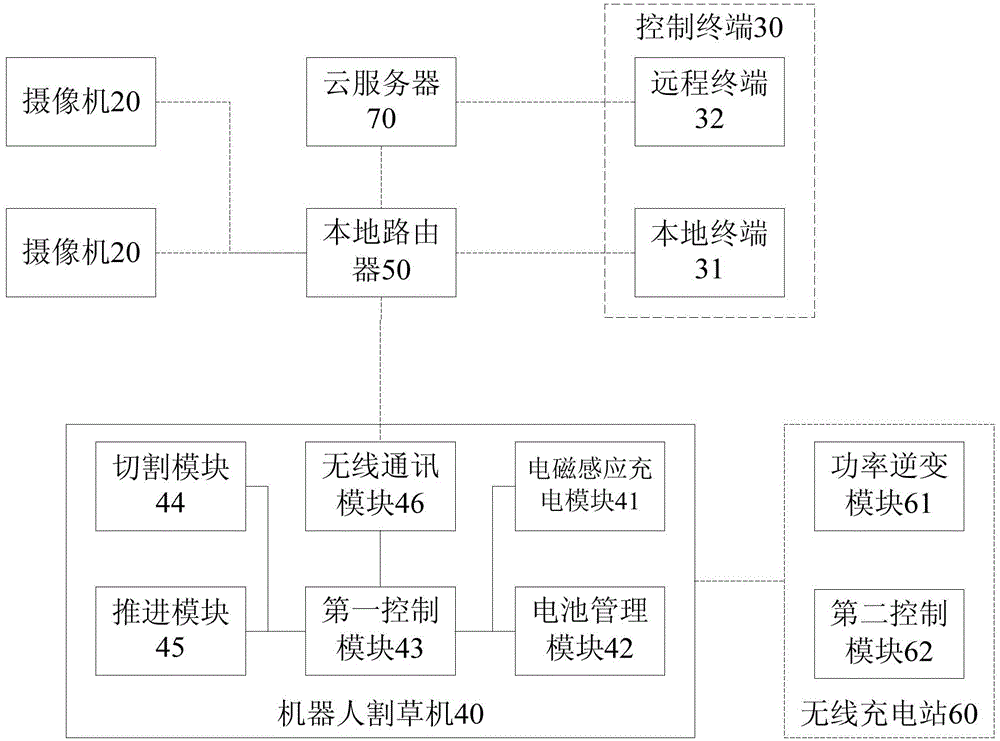
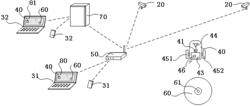
[0039] figure 2 A robot mowing system that can customize a mowing area in an embodiment of the present invention is shown, and the robot mowing system includes: at least one camera 20 , a control terminal 30 , a robot mower 40 and a local router 50 .

[0040] At least one camera 20 is used to collect the mowing area image and send it to the control terminal 30 through the local router 50. It can be understood that the number of cameras 20 can be determined according to the size of the mowing area that needs to be determined. In this embodiment, the customized The mowed area is the coverage area of ​​images of the mowed area captured by one or more cameras 20 .

[0041]The control terminal 30 is used to control at leas...


PUM


Abstract

The invention discloses a robot mowing system capable of customizing mowing zone and a control method of the robot mowing system. The system comprises at least one camera, a control terminal, a robot mowing machine and a local router; the camera is used for collecting an image of the mowing zone and sending the image to the control terminal through a local router; the control terminal is used for controlling the camera to collect the image of the mowing zone, and generating and customizing an environmental drawing of the mowing zone corresponding to the customized mowing zone and a corresponding space coordinate system according to the image of the mowing zone; a first space coordinate (X1, Y1) of the robot mowing machine is marked in the environmental drawing of the mowing zone c; moreover, the control terminal is further used for controlling the work of the robot mowing machine according to a first control instruct input by a user, and monitoring the working state of the robot mowing machine by monitoring the position change of the first space coordinate (X1, Y1) in a space coordinate system. The robot mowing system needs not to preset a boundary lead, and can customize the mowing zone in real time; moreover, the mowing path is more free, and not influenced by the boundary lead.

Description

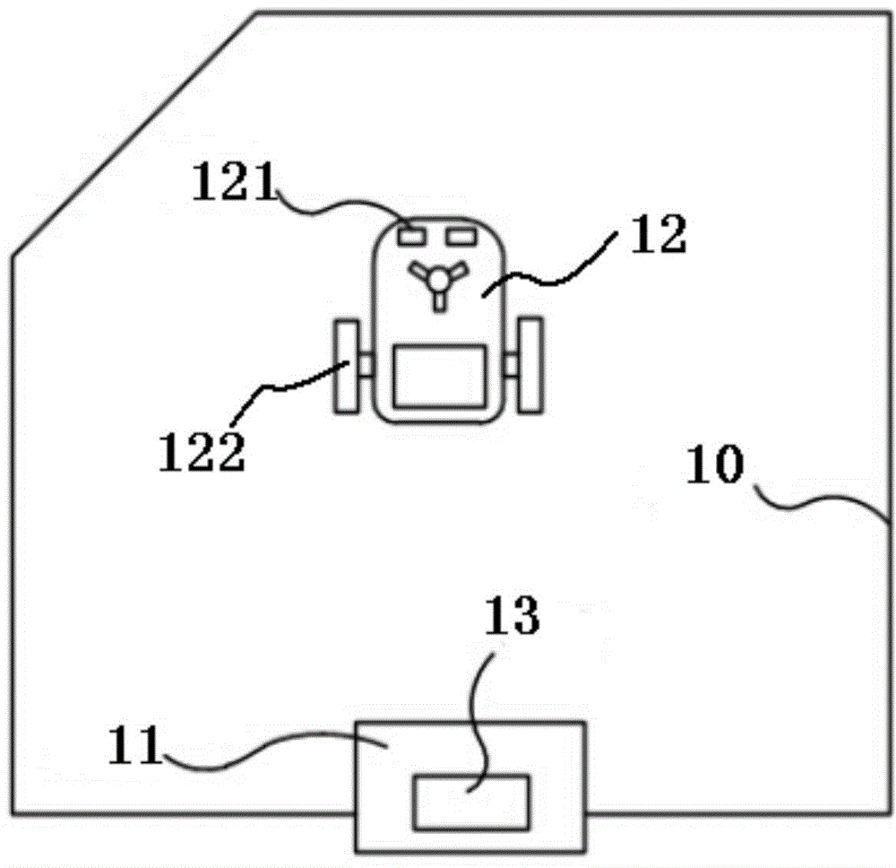
technical field [0001] The robot mowing system of the present invention particularly relates to a robot mowing system capable of customizing a mowing area and a control method thereof. Background technique [0002] At present, the mainstream robot mowing system on the market uses the boundary wire and the boundary sensor component of the robot mower to detect the boundary of the mowing area, such as figure 1 shown. When installing the mainstream robotic lawnmowers currently on the market, it is necessary to pre-arrange the boundary line 10 and install the boundary line signal generator 11. The robotic lawnmower 12 detects the boundary line 10 of the mowing area through its own boundary sensor assembly 121. After receiving the boundary signal, the vehicle control unit 122 controls the behavior of the robot mower 12 to make it turn so as to achieve the purpose of limiting the mowing area. When these robotic lawnmowers 12 need to be charged, the robotic lawnmowers 12 will aut...

Claims


Application Information

Patent Timeline
IPC IPC(8): G05D1/02
CPCG05D1/02G05D1/0282
Inventor 梁峰李瑜
Owner SHENZHEN TOPBAND CO LTD
Learn More