Autorotation Drive Mechanism And Film Label Sticking Device Using The Same

A driving mechanism and label sticking technology, applied in the direction of transmission, electromechanical device, electromechanical transmission, etc., can solve the problems of inconsistent diameter, folded film label, surface damage of film label, etc.

Active Publication Date: 2015-06-10
TOYO SEIKAN GRP HLDG LTD
View PDF1 Cites 1 Cited by
  • Summary
  • Abstract
  • Description
  • Claims
  • Application Information

AI Technical Summary

Problems solved by technology

[0011] However, in the known film label sticking device using the above-mentioned rotation drive mechanism, the diameter of the driven member (roller 21) is set to an optimum rotation speed in other processes, and usually does not match the diameter of the can body. Since the rotation speed of the driven part (roller 21) is not consistent with the rotation speed of the can when it rotates along the pressing pad, the moment the can is in contact with the pressing pad, a force is exerted on the circumference of the can due to the difference in rotation speed. Force, so there are problems such as damage to the surface of the film label due to friction, and wrinkling of the film label

Method used


Image

  • Autorotation Drive Mechanism And Film Label Sticking Device Using The Same
  • Autorotation Drive Mechanism And Film Label Sticking Device Using The Same
  • Autorotation Drive Mechanism And Film Label Sticking Device Using The Same

Examples


Embodiment Construction

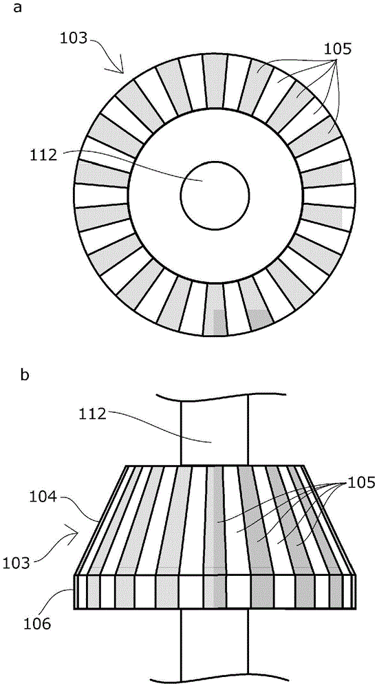
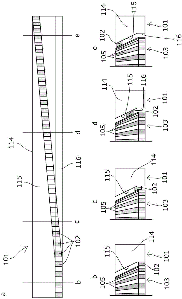
[0036] The autorotation driving mechanism of the present invention includes: a movable driven member having a driven mechanism on a tapered portion and connected to an autorotation shaft; a driving member arranged along the moving direction of the driven member, A transmission mechanism is provided, and the above-mentioned transmission mechanism is arranged to be opposed to any position in the direction of the rotation axis of the above-mentioned driven mechanism.

[0037] Therefore, as long as it is a mechanism that can rotate a plurality of rotation axes while continuously moving without a special driving device or a control device, and can change the rotation speed arbitrarily with a simple structure, its specific structure may be as follows: arbitrary structure.

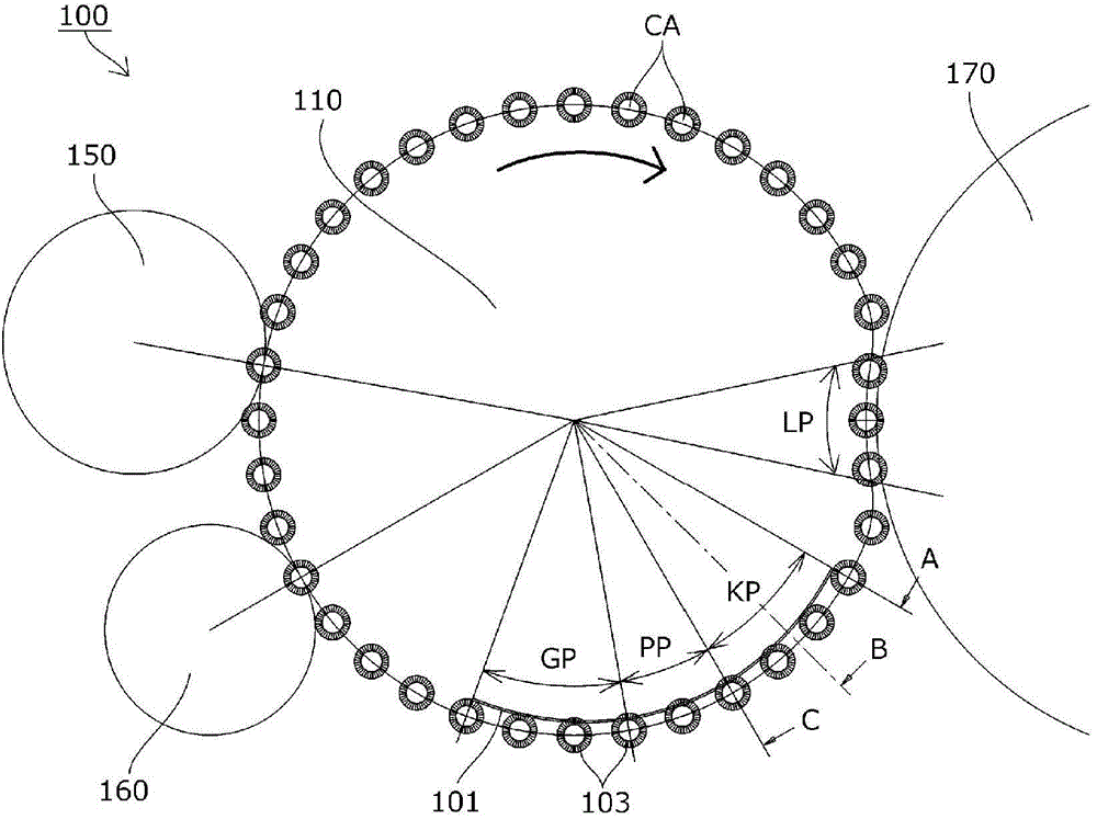
[0038]In addition, the film label sticking device of the present invention is a film label sticking device that continuously moves a plurality of can bodies while rotating on their own, and sticks film labels on ...


PUM


Abstract

Provided are: a rotating drive mechanism which can, without requiring a special drive device and a control device, rotate a large number of rotating shafts while continuously moving the rotating shafts and which is configured so that the rotational speed of the rotating shafts can be arbitrarily changed by a simple configuration; and a film label application device. A rotating drive mechanism is provided with: a movable driven member (103) which has a follower mechanism (105) provided to the tapered section (104) thereof and to which a rotating shaft (112) is connected; and a driving member (101) which is provided along the direction of movement of the driven member (103) and which has a transmission mechanism (102) provided to the sloped section (115) thereof. The transmission mechanism (102) is provided so as to face an arbitrary position of the follower mechanism (105).

Description

technical field [0001] The invention relates to a self-rotating drive mechanism and a film label sticking device using the mechanism. Background technique [0002] Conventionally, as a film label sticking device for sticking a film label on the outer peripheral surface of a can body, there is known a film label sticking device that rotates the can body while moving for film label sticking, pre-processing, post-processing, and the like. [0003] Furthermore, various mechanisms are known for an autorotation drive mechanism for autorotating a tank body while moving. [0004] For example, in a known film label sticking device such as Japanese Unexamined Patent Application Publication No. 2001-179830 (Patent Document 1), it is configured that a film label is sticked to a can body, the can is heated as a pre-processing, and the post-processing is performed. In the process of cooling the cans, the can body is supported by the mandrel 20 of the mandrel rotary conveying mechanism 1,...

Claims


Application Information

Patent Timeline
Patent Type & Authority Applications(China)
IPC IPC(8): F16H49/00B65C9/04
CPCB65C9/04H02K49/102Y10T156/1702B32B37/0046H02K51/00
Inventor 田中宏树
Owner TOYO SEIKAN GRP HLDG LTD
Why Eureka
Try Eureka