
Coating device and coating method

A kind of coating equipment and coating technology, which is applied in the direction of surface coating liquid devices, coatings, printed circuit coatings, etc., can solve the problems of reducing manufacturing efficiency, increasing equipment costs, and film holes, etc., to improve products Quality, equipment cost reduction, and manufacturing time saving effects

Active Publication Date: 2015-06-17
MICROCOSM TECH
View PDF6 Cites 9 Cited by
  • Summary
  • Abstract
  • Description
  • Claims
  • Application Information

AI Technical Summary

Problems solved by technology

[0005] However, in the actual application of the aforementioned two kinds of coating equipment, since the surface of the substrate is usually provided with lines, the installation surface is uneven and blind holes or through holes are formed.
Therefore, when the aforementioned two kinds of coating devices apply a quantitative amount of ink to one of the setting surfaces of the substrate, because the amount of ink is fixed, when part of the ink is filled into the blind hole or When it is in the through hole, it will cause holes and discontinuity in the film layer covering the blind hole or near the through hole
In addition, the above two methods of coating equipment only apply the ink to the installation surface of the substrate. If the ink used has a high viscosity and low fluidity, the ink may not be completely filled on the above-mentioned surface. Blind holes or through holes, resulting in air bubbles between the prepared film layer and the substrate, thereby reducing product quality and aesthetics
[0006] More importantly, the aforementioned two kinds of coating equipment can only coat the ink on one of the setting surfaces of the substrate in a single process. When coating ink, after coating one of the setting surfaces, it is often necessary to roll up the substrate before using the coating equipment to coat the other setting surface
The manufacturing method of the above-mentioned two processes not only reduces the manufacturing efficiency due to the long working time, but also requires more and more complicated equipment components for the aforementioned manufacturing method, thereby increasing the equipment cost

Method used


Image

  • Coating device and coating method
  • Coating device and coating method
  • Coating device and coating method

Examples


Embodiment Construction

[0027] The present invention will be described in detail below with reference to the drawings and embodiments. It should be noted that in the following description, similar components are denoted by the same numbers.

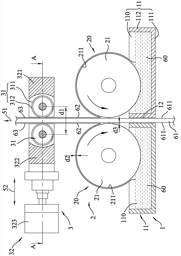
[0028] refer to image 3 , 4 5. A first preferred embodiment of the coating equipment of the present invention is one of the machines used in the process of manufacturing flexible printed circuit boards (Flexible Printed Circuit Board, FPCB for short). When a substrate 61 is transported to the coating device of this embodiment along a vertical direction 51 , the coating device is used to coat the substrate 61 with the viscous ink 60 to coat and form a film layer 63 .

[0029]In this embodiment, the substrate 61 is continuously conveyed from bottom to top along the vertical direction 51 to the coating equipment of this embodiment in a roll-to-roll (Roll To Roll) manner. Of course, in practice, the base material 61 can also be transported in a single sheet (Shee...


PUM


Abstract

The disclosure provides a coating device and a coating method. The coating device is used for coating viscous ink on a substrate to form a film. The substrate includes two opposite mounting surfaces. The coating device comprising: an accommodating mechanism, a coating mechanism and a forming mechanism. The coating mechanism includes two coating units. Each coating unit includes a rotatable filling roller for filling with pressure the viscous ink in the hole on the corresponding mounting surface to form an initial layer. The forming mechanism is used for scraping the initial layer covering on the mounting surfaces to form the film. The method of coating and then adjusting the thickness of the film may improve the quality of the products. By using the above disclosure, the production line can be simplified to lower the device costs, and the manufacturing time can be reduced to improve the manufacturing efficiency.

Description

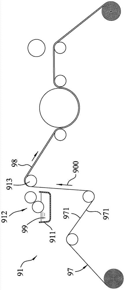
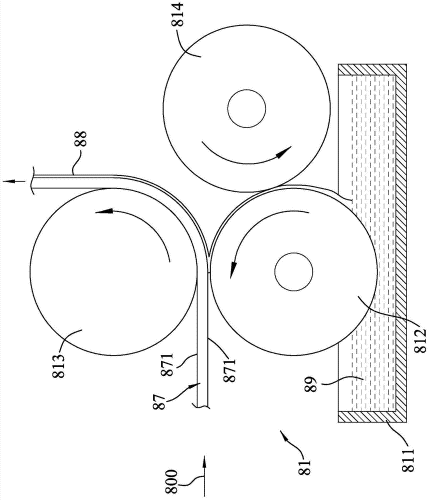
technical field [0001] The invention relates to a coating device and a coating method, in particular to a coating device and a coating method for coating viscous ink on a base material in the process of manufacturing a flexible printed circuit board. Background technique [0002] Generally, the manufacturing of a flexible printed circuit board (FPCB for short) usually needs to go through processes such as photoresist coating, exposure, development, etching, ink coating and baking. Among them, as far as the process of coating ink is concerned, ink is usually coated on a substrate by a coating device to coat and form a film layer. The aforementioned film layer can provide insulation protection and protect copper wires from electrons. Parts are soldered to incorrect places. [0003] refer to figure 1 , a kind of coating equipment 91 that Chinese Taiwan Patent Certificate No. M418024 new patent discloses, comprises a base 911 that ink material 99 is housed, a coating roller un...

Claims


Application Information

Patent Timeline
Patent Type & Authority Applications(China)
IPC IPC(8): B05C1/08B05C9/04B05C11/02
CPCB05C1/0808B05C9/04B05C11/02H05K3/0091H05K3/282H05K2203/1518H05K2203/1545H05K2203/1572
Inventor 黄堂傑
Owner MICROCOSM TECH
Learn More