
Stamping forming method and mold for special-shaped powder metallurgy products

A powder metallurgy and mold technology, which is used in the design of powder metallurgy non-standard products automatic pressing and molding mold design, and the design of special-shaped non-standard product molds, which can solve the problem of reducing product performance, large gap between low-end and high-end densities of inclined planes, and low production efficiency. problems, to ensure product quality, ensure uniformity, and improve production efficiency.

Active Publication Date: 2017-12-26
江西江钨硬质合金有限公司
View PDF12 Cites 0 Cited by
  • Summary
  • Abstract
  • Description
  • Claims
  • Application Information

AI Technical Summary

Problems solved by technology

[0004] Existing technology adopts manual packing to press, and production efficiency is extremely low, only adopts automatic pressing to improve productivity, and adopts traditional mold design concept (such as Image 6 , Figure 7 As shown), the product slope is filled with too much flour, which leads to an excessive density gap between the low end and the high end of the slope, thereby reducing product performance
[0005] In order to improve productivity while ensuring product quality exploration, there are few existing technologies
[0006] In particular, those skilled in the art have formed the prejudice of traditional technology, that is, they think that the mold design should be a traditional isotropic symmetric structure, and no one has ever considered designing a mold of the opposite sex accordingly, and no one has tried to change the traditional mold punch. Head Design Principles

Method used


Image

  • Stamping forming method and mold for special-shaped powder metallurgy products
  • Stamping forming method and mold for special-shaped powder metallurgy products
  • Stamping forming method and mold for special-shaped powder metallurgy products

Examples


Embodiment Construction

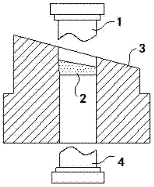
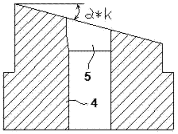
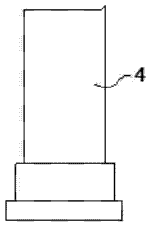
[0032] in the attached Figure 1-7 Among them, the reference numeral 1 represents the upper punch of the automatic compression molding die; the reference numeral 2 represents the molding area for product pressing; the reference numeral 3 represents the automatic compression molding mold; the reference numeral 4 represents the lower punch of the automatic compression molding die Head; Reference numeral 5 represents the packing area filled with mold powder of the present invention; Reference numeral 6 represents the mold of traditional automatic pressing; Reference numeral 7 represents the filling area of ​​traditional automatic pressing die powder filling, wherein, α is The slope angle of the product of the present invention, α*k is the design slope angle of the mold of the present invention and the design angle of the punch on the mold, and k is the design shrinkage coefficient of the mold.

[0033] The present invention will be further described below in conjunction with acco...


PUM

PropertyMeasurementUnit
shrinkage factoraaaaaaaaaa

Abstract

The invention provides a special-shaped powder metallurgical product punch forming method. A special-shaped powder metallurgical product is provided with at least one inclined face and is characterized in that a punching die is provided with a die inclined face with the angle corresponding to that of the inclined face, and the proportion between the angle of the inclined face of the die and the angle of the inclined face is a shrinkage coefficient of the die. Particularly, a filling opening of a traditional horizontal powder filling area is changed to the inclined angle provided with the die inclined face. Powder filling of the filling opening of the powder filling area is applicable to the inclination angle of the inclined face of the die. Correspondingly, powder filling of the powder filling area is reduced, filling of abundant powder is avoided, and accordingly uniform density of the product is guaranteed. The method facilitates uniform and automatic filling and facilitates automatic production of a pressing machine, product quality is stable, and productivity is high.

Description

technical field [0001] The invention relates to a stamping forming method and mold for special-shaped powder metallurgy products, in particular to the design technology of automatic press-forming molds for powder metallurgy non-standard products, especially to the design of molds for special-shaped non-standard products with inclined surfaces at one end or both ends, which is convenient for evenly and automatically Filling can be produced on automatic presses to ensure the stability of product quality and increase productivity. Background technique [0002] Powder metallurgy special-shaped non-standard products are widely used in industry, and the demand for special-shaped non-standard products with slopes at one or both ends has been high. [0003] In production, because one or both ends of this type of product have slopes, the amount and uniformity of powder filling during molding directly affect the product quality. [0004] Existing technology adopts manual packing to p...

Claims


Application Information

Patent Timeline
Patent Type & Authority Patents(China)
IPC IPC(8): B22F3/02B22F3/03B22F5/00
Inventor 欧立明陈辉
Owner 江西江钨硬质合金有限公司
Learn More