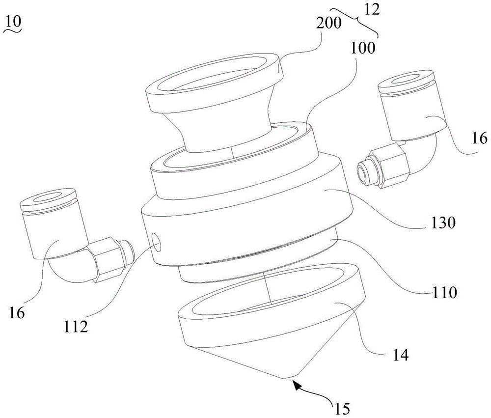
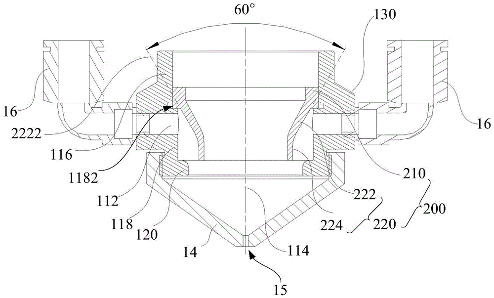
Cutting nozzle air chamber device and cutting nozzle system

A cutting nozzle and airflow cavity technology, applied in the field of lasers, can solve the problems of excessive cutting size, slag hanging on the cutting surface, slow cutting airflow speed, etc., and achieve the effect of precise cutting accuracy, high-speed cutting efficiency, and improving cutting accuracy.

Active Publication Date: 2016-09-14
HANS LASER TECH IND GRP CO LTD
View PDF7 Cites 0 Cited by
  • Summary
  • Abstract
  • Description
  • Claims
  • Application Information

AI Technical Summary

Problems solved by technology

[0005] However, the existing airflow cavity of the cutting nozzle can no longer meet the needs of the product. Often the cutting airflow speed at the cutting nozzle is too slow to blow out the particles and smoke generated by laser cutting in time, which makes the cutting size out of tolerance, and slag hangs on the cutting surface. Phenomena such as slow speed
Sometimes dust can also contaminate the focusing lens, further reducing cutting efficiency and quality

Method used


Image

  • Cutting nozzle air chamber device and cutting nozzle system
  • Cutting nozzle air chamber device and cutting nozzle system
  • Cutting nozzle air chamber device and cutting nozzle system

Examples


Embodiment Construction

[0036] In order to facilitate the understanding of the present invention, the cutting nozzle airflow chamber device and the cutting nozzle system of the present invention will be more fully described below with reference to the relevant drawings. Preferred embodiments of the invention are shown in the accompanying drawings. However, the present invention can be embodied in many different forms and is not limited to the embodiments described herein. On the contrary, these embodiments are provided to make the understanding of the disclosure of the present invention more thorough and comprehensive.

[0037] It should be noted that when an element is referred to as being “fixed” to another element, it can be directly on the other element or there can also be an intervening element. When an element is referred to as being "connected to" another element, it can be directly connected to the other element or intervening elements may also be present.

[0038] Unless otherwise defined...


PUM


Abstract

The invention relates to a cutting nozzle airflow cavity device and a cutting nozzle system. The cutting nozzle airflow cavity device comprises a cutting nozzle airflow cavity which comprises a barrel body, one end of the barrel body is used for being connected with a cutting nozzle, the other end of the barrel body is used for being connected with a focus lens seat, mounting holes used for mounting air pipe connectors are formed in the barrel body, the center lines of the mounting holes are perpendicular to the center line of the barrel body, and the multiple mounting holes are arranged at equal intervals; a cutting nozzle airflow isolated body which is of a hollow structure is arranged in the barrel body and comprises a connection portion and a spacing portion which is connected with the connection portion, the spacing portion is near one end, used for being connected with the cutting nozzle, of the barrel body, the outer wall of the connection portion is connected with the inner wall of the barrel body in a sealed mode, and the outer wall of the spacing portion and the inner wall of the barrel body are in a spaced mode, wherein the mounting holes are located between the two ends of the spacing portion. The cutting nozzle airflow cavity device has the advantages of being precise in cutting precision, good in cutting quality and high in cutting efficiency.

Description

technical field [0001] The invention relates to the technical field of lasers, in particular to a cutting nozzle airflow cavity device and a cutting nozzle system. Background technique [0002] Laser cutting is to use the high-power and high-density focused laser beam instantly generated by the laser to scan the surface of the material to melt or vaporize the material instantly, and then use high-pressure gas to blow the melted or vaporized material away from the slit, so as to achieve the purpose of cutting the material. [0003] The materials that can be cut by laser are becoming more and more abundant, and its application fields and development are becoming more and more mature, and the requirements for the finished products after cutting are also getting higher and higher. The finished products after cutting should meet precise cutting accuracy, good cutting quality and high-speed cutting efficiency. [0004] The role of the cutting airflow is becoming more and more imp...

Claims


Application Information

Patent Timeline
Patent Type & Authority Patents(China)
IPC IPC(8): B23K26/14B23K26/38
CPCB23K26/1476B23K26/38
Inventor 官伟邵雨化张善基吴奎陈育钦高云峰
Owner HANS LASER TECH IND GRP CO LTD
Why Eureka
Try Eureka