

Integrated electro-hydraulic brake system
Patent Information
- Authority / Receiving Office
- CN · China
- Patent Type
- Applications(China)
- Current Assignee / Owner
- HL MANDO CORP
- Publication Date
- 2015-06-17
Smart Images
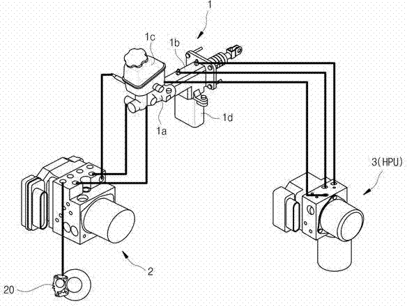
Figure 1 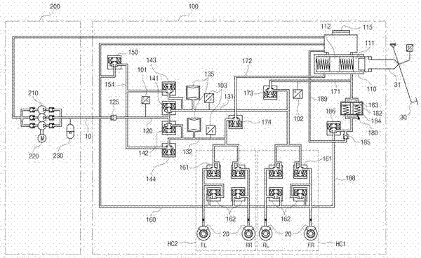
Figure 2 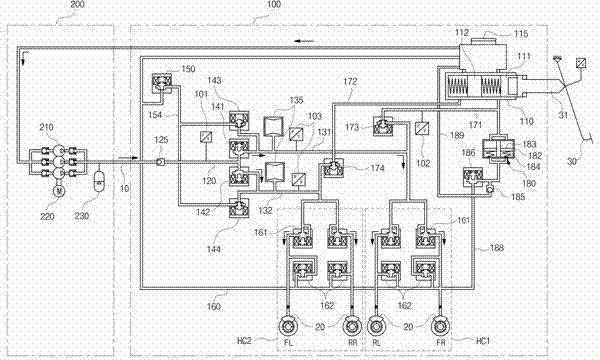
Figure 3
Abstract
Description
[0001] This application claims priority from Korean Patent Application No. P2013-0155090 filed December 13, 2013, the disclosure of which is incorporated herein by reference. technical field
[0002] The present invention relates to an electro-hydraulic braking system, and in particular, to an integrated electro-hydraulic braking system that provides an actuator including a master cylinder, a pedal simulator, etc., an electronic stability control (ESC), and as A hydraulic power unit (HPU) of a single unit. Background technique
[0003] Recently, in order to improve fuel efficiency and reduce exhaust gas, hybrid vehicles, fuel cell vehicles, electric vehicles, etc. have been actively developed. A braking device, that is, the braking device of a vehicle braking system, must be installed in such vehicles. Here, the vehicle braking system refers to reducing the speed of a traveling vehicle or stopping the vehicle.
[0004] A braking device of a common automobile braking system...