Car lamp

A technology of car lights and LED lights, which is applied in the field of lighting, can solve problems such as increasing product production costs, reducing product yield, and complicated processes, and achieves the effects of avoiding damage, improving service life, and beautiful appearance

Inactive Publication Date: 2015-06-17
杨道达
8 Cites 0 Cited by

AI-Extracted Technical Summary

Problems solved by technology

First of all, the external placement of the power lead or the circuit board will lead to poor connection between the power lead and the light source area, making the process complicated, thereby reducing the product yield rate and increasing...

Method used

4. In the car light of the present invention, the first cylinder and the second cylinder are all provided with through holes 13, and the through holes 13 are connected to the wiring groove 15 and the light-emitting area 12, so that the wires, circuit boards or conductive rods Extends therefrom to the light-emitting region 12 . In this way, the power leads can be electrically connected to the chip or the LED lamp 20 in the light-emitting area 12 , so that the wiring is simple and the appearance is beautiful.
Please refer to Fig. 1-5, Fig. 1-4 has shown the first column body or the second column body structural diagram that is used for circuit board transfer mode, Fig. 5 has schematically shown the circuit built in the column body 10 Plate 30 structure. A circuit board 30 is arranged in the passage, please refer to FIG. 5 again, the circuit board 30 is connected with a first bending plate 31, and the first bending plate 31 protrudes from the through hole 13 and is attached to the The light emitting area 12. Referring to Fig. 1 or 3 again, the light-emitting area 12 is provided with a first groove 14 connected to the through hole 13, and the first bent plate 31 is pasted in the first groove 14 after passing through the through hole 13. , making the structure more compact and beautiful in appearance.
Please refer to Fig. 6-10, and Fig. 6-9 has shown the first cylinder or the second cylinder structural diagram that is used for conducting rod transfer mode, and Fig. 10 has shown that the conductive rod built in the cylinder 10 Rod transfer structure. A circuit board 40 is disposed in the passage, please refer to FIG. 10 again, the circuit board 40 is electrically connected with a first conductive rod 41 , and the first conductive rod 41 extends out of the through hole 13 . The circuit board 40 is electrically connected with a second conductive rod 42, and the second conductive rod 42 protrudes from between the first part of the light-emitting area and the second part of the light-emitting area. Please refer to F...

Abstract

The invention discloses a car lamp. The car lamp comprises a pole and wafers or LED lights. The sidewall of the pole is provided with a light emitting region. The wafers or the LED lights are arranged on the light emitting region. A channel is formed in the pole. One end of the pole is communicated with the bottom of the pole. The other end of the channel is communicated with the light emitting region. According to the car lamp, the channel is arranged in the pole, and the sidewall of the pole is provided with the light emitting region; a power lead can leads to the light emitting region on the sidewall of the pole through the channel in the pole and is electrically connected with the wafers or the LED lights, so the power lead is prevented from being exposed out of the pole. In this way, the power lead or a circuit board of the car lamp is arranged in the lamp pole, the car lamp is simple in structure, attractive in appearance, reasonable in layout and capable of preventing the power lead from being damaged, and the service life of the lamp pole can be prolonged.

Application Domain

Point-like light sourceElectric circuit arrangements +5

Technology Topic

EngineeringLED lamp +1

Image

  • Car lamp
  • Car lamp
  • Car lamp

Examples

  • Experimental program(1)

Example Embodiment

[0032] Embodiments of the present invention are described in detail below:
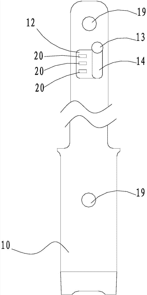
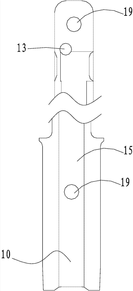
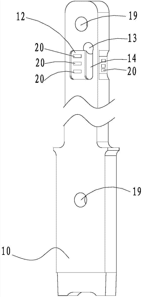
[0033] like Figure 1-4 , As shown in any of 6-9, the vehicle lamp of the present invention includes a cylinder 10, a chip or an LED lamp 20. The side wall of the column 10 has a light-emitting area 12 , the chip or the LED lamp 20 is disposed in the light-emitting area 12 , and a channel (not shown in the figure) is provided inside the column 10 . One end of the channel is connected to the bottom of the column body 10 , and the other end of the channel is connected to the light-emitting area 12 .
[0034] In the vehicle lamp of the present invention, a channel is arranged inside the column body 10 , and a light-emitting area 12 is arranged on the side wall of the column body 10 . The power leads can be routed from the channel inside the column 10 to the light emitting area 12 on the sidewall of the column 10 and electrically connected to the chip or the LED lamp 20 to prevent the power leads from being exposed outside the column 10 . It can be seen that the power lead or circuit board of the vehicle lamp of the present invention is built in the lamp post, has a simple structure, beautiful appearance, reasonable layout, can avoid damage to the power lead, and can improve the service life of the lamp post.
[0035] The number of the light-emitting areas 12 is more than two, and the two or more light-emitting areas 12 are arranged around the column body 10 , and the light-emitting areas 12 are arranged with more than one chip or LED lamp 20 .
[0036] The column body 10 is divided into a first column body and a second column body (not shown in the figure) along the axial direction. The first column body and the second column body are respectively provided with installation holes 19 and are fastened by tightening. The first column body is fastened with the second column body by inserting the component into the mounting hole. The first column body and the second column body are both provided with a wiring slot 15 , one end of the wiring slot 15 is located at the bottom of the column 10 , and the other end of the wiring slot 15 is connected to the light emitting area 12 . Corresponding positions, the wiring slot 15 of the first column is spliced ​​with the wiring slot 15 of the second column to form the channel.
[0037] The cross section of any section of the column body 10 where the light emitting area 12 is located is rectangular, and the column body 10 is surrounded by four light emitting areas 12 . The four light-emitting regions 12 are arranged opposite each other in pairs. The two opposite light-emitting areas 12 of the first group are respectively located on the first column and the second column, and the two opposite light-emitting areas 12 of the second group are divided into a first partial light-emitting area and a second partial light-emitting area ( Not shown in the figure), the first part of the light-emitting area is located on the first cylinder, and the second part of the light-emitting area is located on the second cylinder.
[0038] The first column body and/or the second column body is provided with a through hole 13 , one end of the through hole 13 is communicated with the light emitting area 12 , and the other end of the through hole 13 is communicated with the wiring slot 15 .
[0039] see Figure 1-5 , Figure 1-4 It shows the structure diagram of the first column or the second column used for the circuit board transfer method, Figure 5 The structure of the circuit board 30 built into the column body 10 is illustrated. A circuit board 30 is arranged in the channel, please refer to Figure 5 The circuit board 30 is connected with a first bending plate 31 , and the first bending plate 31 extends from the through hole 13 and is attached to the light-emitting area 12 . see again figure 1 Or 3, the light-emitting area 12 is provided with a first groove 14 connected with the through hole 13, and the first bending plate 31 is placed in the first groove 14 after passing through the through hole 13, so that the structure is more compact , and the appearance is beautiful.
[0040]There are two circuit boards 30 , and the first bending plates 31 of the two circuit boards 30 respectively protrude from the through holes 13 of the first cylinder and the second cylinder and are attached to the light-emitting area. 12. The circuit board 30 is connected with a second bending plate 32, the second bending plate 32 protrudes from the first part of the light-emitting area and the second part of the light-emitting area and is attached to the first part to emit light. The light-emitting region 12 is formed by splicing the second partial light-emitting region with the light-emitting region.
[0041] see Figure 6-10 , Figure 6-9 Shows the structure diagram of the first cylinder or the second cylinder used for the transfer mode of the conductive rod, Figure 10 The conductive rod transfer structure built in the column body 10 is illustrated. A circuit board 40 is arranged in the channel, please refer to Figure 10 , the circuit board 40 is electrically connected with a first conductive rod 41 , and the first conductive rod 41 extends out of the through hole 13 . The circuit board 40 is electrically connected with a second conductive rod 42, and the second conductive rod 42 protrudes from the first part of the light-emitting area and the second part of the light-emitting area, please refer to Figure 7 Or 8, the light-emitting area 12 is provided with a second groove 17 for installing the second conductive rod 42, so that the internal structure of the column is compact and stable. Both ends of the first conductive rod 41 protrude from the through holes 13 of the first cylinder and the second cylinder respectively, and both ends of the second conductive rod 42 respectively protrude from both sides of the first cylinder and the second cylinder, The chips or the LED lamps 20 in the four light-emitting areas 12 of the column 10 can be electrically connected to the circuit board 40 .
[0042] To sum up, the present invention has the following advantages:
[0043] 1. In the vehicle lamp of the present invention, a channel is arranged inside the column body 10 , and a light-emitting area 12 is arranged on the side wall of the column body 10 . The power leads can be routed from the channel inside the column 10 to the light emitting area 12 on the sidewall of the column 10 and electrically connected to the chip or the LED lamp 20 to prevent the power leads from being exposed outside the column 10 . It can be seen that the power lead or circuit board of the vehicle lamp of the present invention is built in the lamp post, has a simple structure, beautiful appearance, reasonable layout, can avoid damage to the power lead, and can improve the service life of the lamp post.
[0044] 2. In the vehicle lamp of the present invention, more than one light-emitting area 12 is arranged around the side wall of the column 10, and a chip or LED lamp 20 is arranged in the light-emitting area 12, so that the vehicle lamp can emit light in 360 degrees.
[0045] 3. In the vehicle lamp of the present invention, the column body 10 is formed by splicing a first column body and a second column body. A circuit board can be installed in the channel.
[0046] 4. In the vehicle lamp according to the present invention, the first column body and the second column body are provided with through holes 13, and the through holes 13 connect the wiring groove 15 and the light-emitting area 12, so that the wires, circuit boards or conductive rods extend therefrom. out to the light-emitting area 12 . In this way, the power lead can be electrically connected to the chip or the LED lamp 20 in the light emitting area 12, so that the wiring is simple and the appearance is beautiful.
[0047] 5. The vehicle lamp of the present invention can adopt a circuit board bending and switching method, that is, the first bending plate 31 extends out of the through hole 13, and the second bending plate 32 emits light from the first part of the light-emitting area and the second part. The first bending plate 31 and the second bending plate 32 are electrically connected to the chip or the LED lamp 20 respectively; the conductive rod transfer method can also be adopted, that is, the first conductive rod 41 can be connected from the The hole 13 protrudes, the second conductive rod 42 protrudes from between the first part of the light-emitting area and the second part of the light-emitting area, and then the first conductive rod 41 and the second conductive rod 42 are electrically connected to the chip or the LED lamp 20 respectively.
[0048] The technical features of the above-described embodiments can be combined arbitrarily. For the sake of brevity, all possible combinations of the technical features in the above-described embodiments are not described. However, as long as there is no contradiction between the combinations of these technical features, All should be regarded as the scope described in this specification.
[0049] The above-mentioned embodiments only represent several embodiments of the present invention, and the descriptions thereof are more specific and detailed, but should not be construed as a limitation on the scope of the invention patent. It should be pointed out that for those skilled in the art, without departing from the concept of the present invention, several modifications and improvements can be made, which all belong to the protection scope of the present invention. Therefore, the protection scope of the patent of the present invention should be subject to the appended claims.

PUM

no PUM

Description & Claims & Application Information

We can also present the details of the Description, Claims and Application information to help users get a comprehensive understanding of the technical details of the patent, such as background art, summary of invention, brief description of drawings, description of embodiments, and other original content. On the other hand, users can also determine the specific scope of protection of the technology through the list of claims; as well as understand the changes in the life cycle of the technology with the presentation of the patent timeline. Login to view more.

Similar technology patents

Body condition measuring device

InactiveUS20050234351A1simple structure
Owner:DENSO CORP

Magnetic cooling apparatus and control method thereof

ActiveUS20130180263A1simple structure
Owner:SAMSUNG ELECTRONICS CO LTD

Dual-Drivetrain of Power-Assist Vehicle

InactiveUS20100181130A1enhance uphill momentumsimple structure
Owner:CHOU WEN CHENG

Classification and recommendation of technical efficacy words

Why Eureka
Try Eureka