Online power monitoring device for high-power all-fiber laser device and packaging method thereof

A power monitoring and laser technology, which is applied in the direction of using electric radiation detectors for photometry, etc., can solve the problems of interference of measurement values, large errors, and low accuracy of measurement results, and achieves fast response speed, high accuracy, and outstanding essence. effects of sexuality

Inactive Publication Date: 2015-06-17
INST OF APPLIED ELECTRONICS CHINA ACAD OF ENG PHYSICS
View PDF8 Cites 18 Cited by
  • Summary
  • Abstract
  • Description
  • Claims
  • Application Information

AI Technical Summary

Problems solved by technology

The patent proposes two schemes. The first scheme utilizes the correlation between the output laser and the residual pump light. However, since the output laser and the residual pump light are not linearly correlated, subsequent data processing is difficult and has large errors.
In the second solution, the patent adds a fiber fusion splicing point to the pump stripper, so that part of the fiber core laser can be detected, but since the surface of the pump stripper is high-refractive index glue, the loss of the splice point here will be scattered. It is quickly exported and generates serious heat, so the operation risk is very high when it is applied in a high-power all-fiber laser, and because the detector receives the pump light and the fiber core laser at the same time, the measurement value is disturbed, so the measurement result is accurate degree is not high

Method used


Image

  • Online power monitoring device for high-power all-fiber laser device and packaging method thereof
  • Online power monitoring device for high-power all-fiber laser device and packaging method thereof
  • Online power monitoring device for high-power all-fiber laser device and packaging method thereof

Examples


Embodiment Construction

[0028] All features disclosed in this specification, or steps in all methods or processes disclosed, may be combined in any manner, except for mutually exclusive features and / or steps.

[0029] Any feature disclosed in this specification (including any appended claims, abstract and drawings), unless expressly stated otherwise, may be replaced by alternative features which are equivalent or serve a similar purpose. That is, unless expressly stated otherwise, each feature is one example only of a series of equivalent or similar features.

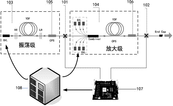
[0030] figure 1It is the application of the monitoring device of the present invention in a common MOPA structure fiber laser, especially the installation position of the monitoring device in the laser. The monitoring devices 101, 102 involved in the present invention should be installed at the welding point between the output of each level of laser (103, 104) and the next level, and must be installed after the pump stripper 105, 106, which i...


PUM


Abstract

The invention provides an online power monitoring device for a high-power all-fiber laser device and a packaging method thereof. Low-refractive-index coating glue is applied to a welding point between each output level of the all-fiber laser device and the next output level of the all-fiber laser device, so that the optical fiber welding points are reinforced, a metal clamp to which a photoelectric detector is fixed and the corresponding welding point are packaged together, the online power monitoring device is attached to a laser device cooling heat sink, and heat generated by the welding point and a photoelectric detector is carried away through heat conduction between the metal clamp and the heat sink. In this way, optical fibers can not be damaged, and the whole all-fiber laser device can not be damaged; furthermore, the photoelectric detector is high in response speed, so that quick online monitoring of the power of the laser device can be achieved in real time; due to the fact that closed-loop control is achieved between the online power monitoring device and a power supply of a laser device system, the laser device system can be effectively protected, and a measured power value is high in accuracy.

Description

technical field [0001] The invention relates to the technical field of laser monitoring, in particular to a high-power all-fiber laser online power monitoring device and a packaging method thereof. Background technique [0002] On-line power monitoring of high-power all-fiber lasers is of great significance to protect the safe operation of engineered lasers. For high-power solid-state lasers with MOPA structures, all-fiber lasers are often used as seed sources. If the power of the fiber laser is abnormal during the entire laser operation process, it will affect the performance of the entire laser system, and in severe cases, it will cause damage to the entire subsequent amplification link. On the other hand, for the high-power all-fiber laser itself, dangers such as fiber fuse are prone to occur during operation, and the fiber fuse will travel reversely along the fiber link at a very fast speed. If the laser power is not turned off in time, the entire all-fiber The laser li...

Claims


Application Information

Patent Timeline
Patent Type & Authority Applications(China)
IPC IPC(8): G01J1/42
Inventor 张凯李腾龙冉欢欢马毅孙殷宏王岩山
Owner INST OF APPLIED ELECTRONICS CHINA ACAD OF ENG PHYSICS
Why Eureka
Try Eureka