Acoustic wave test coupling device and test method thereof

A technology of a coupling device and a test method, which is applied in the direction of material analysis using acoustic wave emission technology, can solve problems such as the inability to guarantee the authenticity and accuracy of test results, the inability to ensure good coupling between water and acoustic wave probes, and the impact of test data, etc., to achieve Accurate and reliable test results, good coupling, widely used effects

Active Publication Date: 2015-06-17
INST OF ROCK & SOIL MECHANICS CHINESE ACAD OF SCI
View PDF8 Cites 11 Cited by
  • Summary
  • Abstract
  • Description
  • Claims
  • Application Information

AI Technical Summary

Problems solved by technology

However, the coupling obtained when using the airbag coupling is poor, which has a great impact on the real test data, and there is air interference in the coupling airbag, which cannot ensure good coupling between the water and the acoustic wave probe, which has a great impact on the test results. Guarantee the authenticity and accuracy of its test results

Method used


Image

  • Acoustic wave test coupling device and test method thereof
  • Acoustic wave test coupling device and test method thereof
  • Acoustic wave test coupling device and test method thereof

Examples


Embodiment 1

[0070] Example 1: When the probe hole is downward.

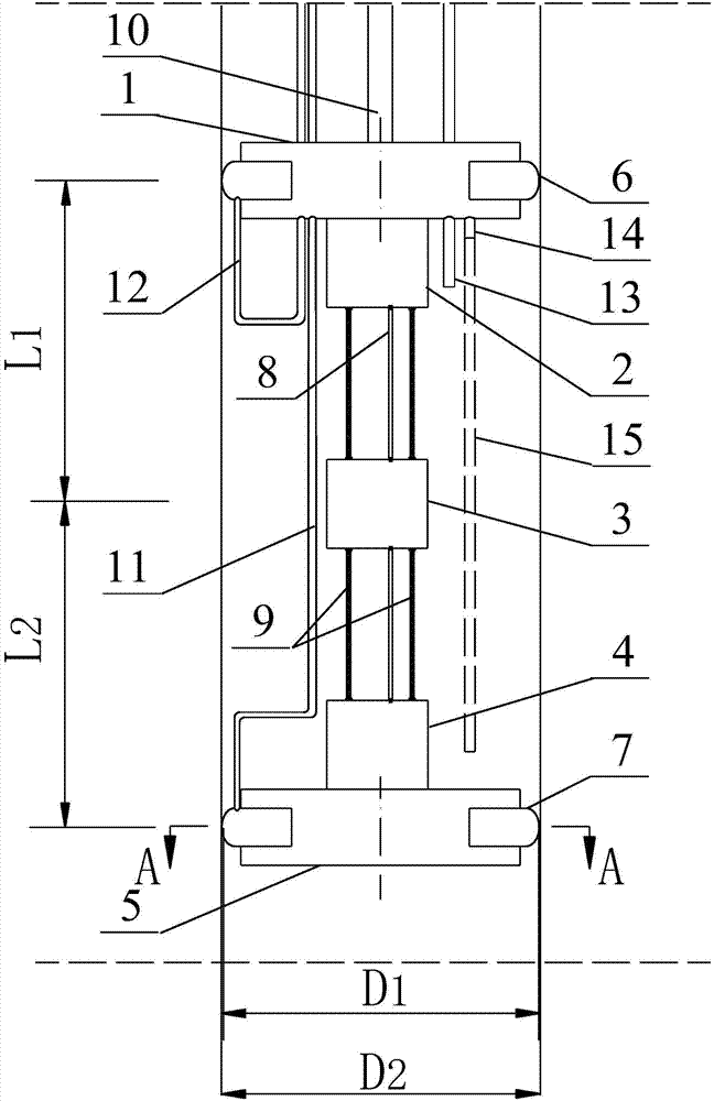
[0071] In this case, the lower exhaust pipe 15 is not required and can be removed.

[0072] Step 1: Place the sonic test coupler into the probe hole and secure it to the test point.

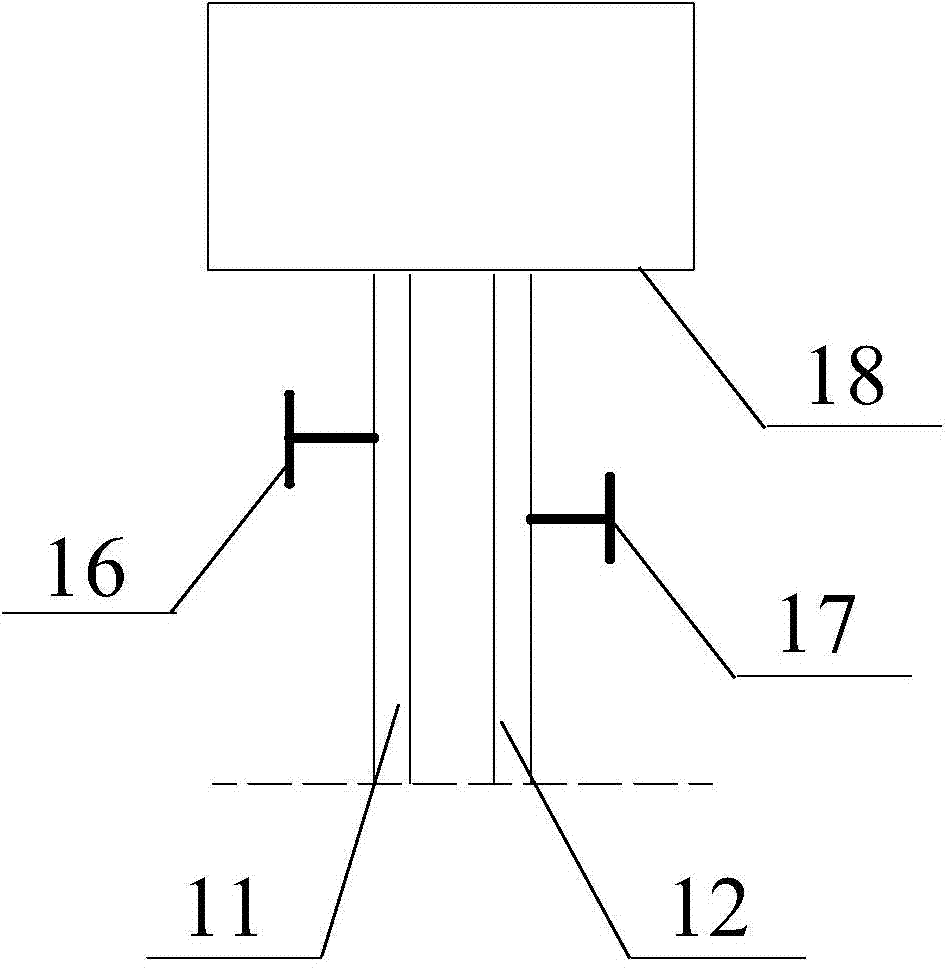
[0073] Step 2: Start the air pump 18, open the bottom airbag valve 17, inflate the bottom airbag 7 through the bottom connecting air pipe 12 until the bottom airbag 7 is closely attached to the wall of the probe hole, and close the bottom airbag valve 17 and the air pump 18.

[0074] Step 3: Open the valve of the water inlet pipe 13, start the water pump, inject water into the probe hole through the water inlet pipe 13, and stop adding water until the water level is close to the top steel ring 1.

[0075] Observe the water level change, and pay attention to whether there is obvious water leakage at the contact surface between the bottom air bag 7 and the probe hole wall; if there is water leakage, continue to open the bottom air bag valve 17, ...

Embodiment 2

[0085] Embodiment 2: when the probe hole is at the class level.

[0086] Step 1 is the same as Step 1 in Example 1.

[0087] Step 2: Open the top airbag valve 16 and the bottom airbag valve 17, and simultaneously inflate the bottom airbag 7 and the top airbag 6 through the bottom connecting air pipe 12 and the top connecting air pipe 11;

[0088] At this moment, the air pressure of the bottom airbag 7 and the top airbag 6 increases at the same speed during the inflation process. However, the situation of the inside airbag (bottom airbag 7 ) can be deduced because only the situation of the outer airbag (top airbag 6 ) can be observed at this time. Close top air bag valve 16, bottom air bag valve 17 and air pump 18 until top air bag 6 is close to the probe hole wall.

[0089] Step 3: Simultaneously open the valves on the upper exhaust pipe 14 and the lower exhaust pipe 15, open the valve on the water inlet pipe 13 and start the water pump to inject water into the probe hole. ...

Embodiment 3

[0099] Example 3: When the probe hole is upward.

[0100] Its operation process is similar to that of drilling downwards. According to the required test points, it is tested from the inside to the outside. It is also due to the gravity of the water and equipment downwards. It is more convenient to operate when moving from top to bottom, and the loss of water in this moving process smaller.

[0101] Step 1 is the same as Example 1.

[0102] Step 2 is the same as Example 2.

[0103] Step 3: Open the valve on the lower exhaust pipe 15, open the valve on the water inlet pipe 13 and start the water pump to inject water into the probe hole.

[0104] If water leaks at the contact between the top airbag 6 and the probe hole wall during the water filling process, open the bottom airbag valve 17 and the top airbag valve 16 again, and use the air pump 18 to inflate the bottom airbag 7 and the top airbag 6 at the same time until there is no water leakage and then close the bottom Air b...


PUM


Abstract

The invention discloses an acoustic wave test coupling device and a test method thereof. The device comprises an acoustic wave emission transducer, a middle acoustic wave receiving transducer and a bottom acoustic wave receiving transducer, wherein a bottom connecting gas tube is arranged in the axial direction of a bottom steel ring in a penetration manner; a bottom connecting gas tube, a top connecting gas tube, a water inlet tube, an upper gas exhausting tube and a lower gas exhausting tube are arranged in the axial direction of the top steel ring in a penetration manner. After being aerated, the edge parts of the top gasbag and the bottom gasbag which respectively sleeve the top steel ring and the bottom steel ring are expanded and clung to the hole wall of a detecting hole to form a sealed test space. The acoustic wave test coupling device can be used for testing after water is injected into the test space. The acoustic wave emission transducer, the receiving transducer and the hole wall are directly coupled through water, the energy transmission loss is extremely small, and good coupling and ring-shaped emitting characteristics and ring-shaped receiving characteristics of acoustic waves are guaranteed, so that an accurate test is realized.

Description

technical field [0001] The invention relates to drilling acoustic wave testing equipment in the field of testing and analyzing the internal structure of rock mass, in particular to an acoustic wave testing coupling device, and also relates to a testing method using the coupling device. Background technique [0002] With the complexity of engineering construction and the improvement of engineering geological requirements, we often need to test the structural conditions and mechanical properties of the rock and soil of the engineering site in order to evaluate and make decisions on the design and construction of major geotechnical engineering and its impact on the environment. [0003] At present, the quantitative research of geotechnical engineering is carried out by means of acoustic wave testing. Specifically, the electromagnetic excitation method is used to emit sound waves to the medium (such as: rock, rock mass, concrete structure, etc.) through the acoustic wave transmit...

Claims


Application Information

Patent Timeline
Patent Type & Authority Applications(China)
IPC IPC(8): G01N29/14
Inventor 胡大伟郭翰群周辉张传庆杨凡杰卢景景朱勇张帆
Owner INST OF ROCK & SOIL MECHANICS CHINESE ACAD OF SCI
Why Eureka
Try Eureka