

Liquid crystal display screen detecting and assembling device
A technology for assembling devices and liquid crystal screens, applied in nonlinear optics, instruments, optics, etc., can solve problems such as easy crushing of liquid crystal screens and circuit boards, difficulty in meeting large-scale production, and difficulty in controlling strength
- Summary
- Abstract
- Description
- Claims
- Application Information
AI Technical Summary
Problems solved by technology
Method used
Image

Examples
Embodiment 1
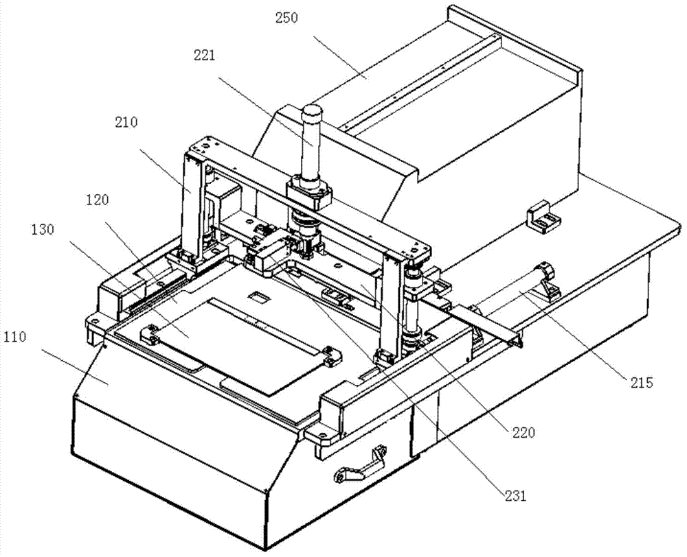
[0089] Such as figure 1As shown, the liquid crystal screen detection and assembly device includes a fixing device, a liquid crystal screen detection device and a liquid crystal screen assembly device. The fixing device is used to support and fix the liquid crystal screen, the liquid crystal screen detection device is arranged under the fixing device, and the liquid crystal screen detection and assembly device is arranged above the fixing device.
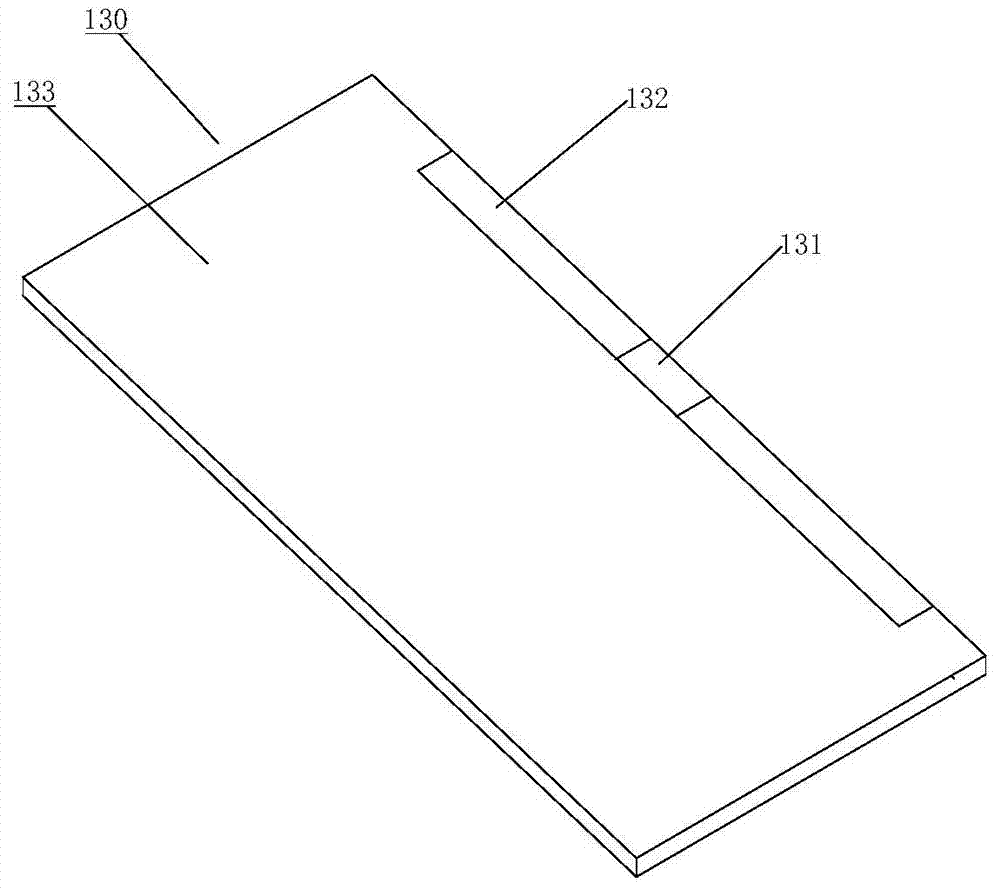
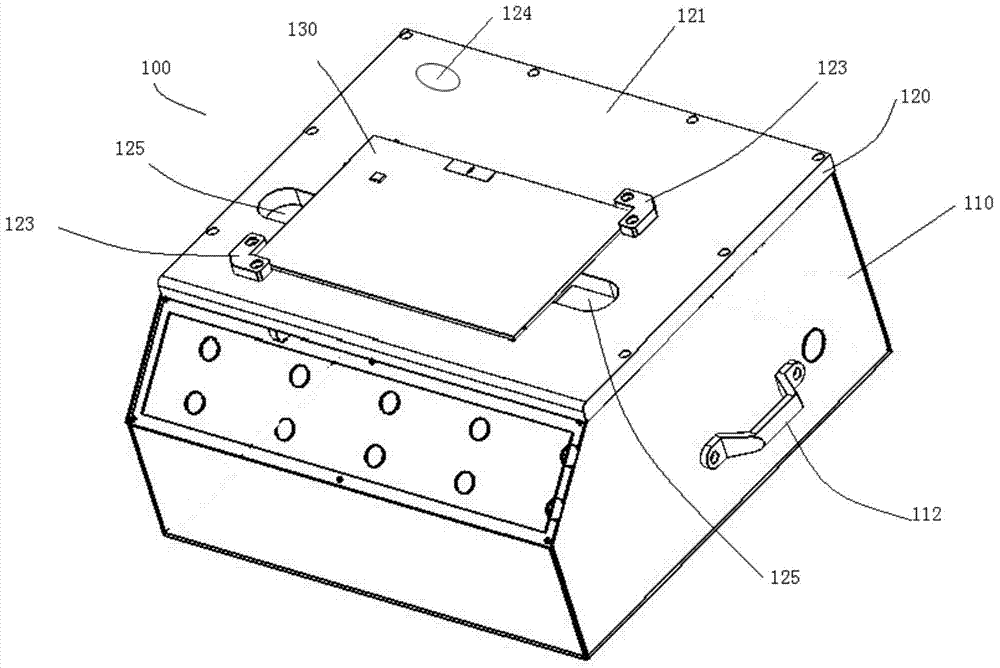
[0090] The fixing device is a support plate 120 for fixing the liquid crystal screen 130 . The upper surface 121 of the support plate 120 is used for fixing the liquid crystal screen 130 . There is a movable signal transmitting device below. The signal transmitting device is used to transmit a signal to the liquid crystal screen 130, and according to the response of the liquid crystal screen 130 to the signal, it can be judged whether the performance of the liquid crystal screen 130 is normal. In the example shown in the figure, t...
Embodiment 2
[0113] Such as Figure 18As shown, the difference between this embodiment and Embodiment 1 is that the air cylinder 190 is used as the first driving device instead of the asynchronous motor 170 in Embodiment 1. The air cylinder 190 is mounted on the lower surface 122 of the support plate 120 . Cylinder 190 is a two-way motion cylinder. The air cylinder 190 includes a cylinder body 191 and a piston rod 192 . The piston rod 192 is telescopically disposed on the cylinder body 191 . The end of the piston rod 192 is connected with the first slider 152 . By adopting the cylinder 190, the present embodiment does not need to use the transmission belt 173 and the driving wheel 172, the supporting wheel 174 and the tensioning wheel 175 matched with the transmission belt 173. The air cylinder 190 communicates with an air supply device (not shown in the figure) through an air supply pipeline, and the air supply device provides an air source. A solenoid valve is set on the gas supply ...
Embodiment 3
[0116] Such as Figure 19 As shown, the difference between this embodiment and Embodiment 1 is that the asynchronous motor 170 , the first guide rail 151 and the first slider 152 in Embodiment 1 are replaced by linear motors. The linear motor includes coil windings 196 and permanent magnet bars 197 . Permanent magnet bars 197 are mounted on the lower surface 122 of the support plate 120 . The coil winding 196 is set on the permanent magnet bar 197 and can move along the permanent magnet bar 197 . Base 160 is mounted on coil winding 196 . By adopting a linear motor, the present embodiment does not need to use an asynchronous motor 170, a transmission belt 173, and a driving wheel 172 matched with the transmission belt 173, a support wheel 174, and a tensioning wheel 175, and the first guide rail 151 and the first slide block 152 are not required. .
[0117] The rest of the structure of this embodiment is the same as that of Embodiment 1.
[0118] The coil winding 196 can b...
PUM
 Abstract
Description
Claims
Application Information