Air conditioner controller, power conversion circuit of air conditioner controller, and power factor correction circuit

A power factor correction and correction circuit technology, applied in the direction of converting AC power input to DC power output, high-efficiency power electronic conversion, output power conversion device, etc., can solve the difficulty of turning on or off multiple switching tubes at the same time, cost and The problems of heavy weight and difficult installation can achieve the effect of reducing size and weight, reducing iron core size and number of winding turns, and small conduction loss

Inactive Publication Date: 2015-06-17
HANGZHOU XIANTU ELECTRONICS
View PDF7 Cites 2 Cited by
  • Summary
  • Abstract
  • Description
  • Claims
  • Application Information

AI Technical Summary

Problems solved by technology

However, although this power factor correction circuit has only one inductor and multiple switch tubes, the multiple switch tubes are turned on or off at the same time. Although this can share the current of the inductor, because the multiple switch tubes are turned on or off at the same time Cut-off, because the control circuit of each switch tube is different, it is difficult to ensure that multiple switch tubes are turned on or off at the same time, and once multiple switch tubes are turned on or off, there is asynchronous situation, such as a fast turn-on , when a conduction is slow, the current flowing through the two switch tubes is bound to be large and the other small, and the device will heat up. Moreover, because multiple switch tubes are turned on or off at the same time, the conduction The on-off frequency is equivalent to the on-off frequency of a switch tube. Due to the limitation of a single switch tube, the operating frequency of the inductor will not be too high, so the volume of a single inductor is still relatively large, which will still cause installation difficulties and Cost and weight issues

Method used


Image

  • Air conditioner controller, power conversion circuit of air conditioner controller, and power factor correction circuit
  • Air conditioner controller, power conversion circuit of air conditioner controller, and power factor correction circuit
  • Air conditioner controller, power conversion circuit of air conditioner controller, and power factor correction circuit

Examples


Embodiment Construction

[0030] Specific embodiments of the present invention will be described below in conjunction with the accompanying drawings.

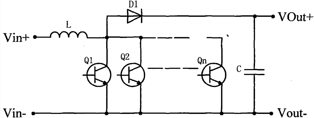
[0031] see figure 1 As shown, it shows a schematic diagram of an embodiment of the power factor correction circuit of the present invention, wherein the power factor correction circuit includes an inductor L, a freewheeling diode D1, a plurality of switching tubes Q1, Q2...Qn and a capacitor C. One end of the inductance L is connected to the positive pole Vin+ of the power supply input terminal, the other end of the inductor L is connected to the positive pole of the freewheeling diode D1, the negative pole of the freewheeling diode D1 is connected to the positive terminal of the capacitor C and the positive pole Vout+ of the power supply output terminal, multiple switches The collectors of the tubes are commonly connected to the node where the inductance L is connected to the positive pole of the freewheeling diode D1, the emitters of multiple switchi...


PUM


Abstract

The invention discloses an air conditioner controller, a power conversion circuit of the air conditioner controller, and a power factor correction circuit. The power factor correction circuit comprises an inductor, a fly-wheel diode, at least two switch tubes and a capacitor, wherein the at least two switch tubes are connected to connection nodes of the inductor and the fly-wheel diode, a loop is formed by the switch tubes and the inductor when the switch tubes are turned on, the inductor discharges through the fly-wheel diode and the capacitor when the switch tubes are turned off, and the at least two switch tubes are turned on alternately under the control of a control circuit. According to the power factor correction circuit, the multiple switch tubes are turned on alternately, the duty ratio is small when the switch tubes are turned on, in this way, breakover losses are small, and the power dissipated at the rated working frequency can meet the requirement for pulse high-power working. Due to the fact that the on-off pulse frequency of the multiple switch tubes is multiple times that of a single switch tube, the inductor can work at a high frequency, the size of an iron core of the inductor and the number of turns of a winding of the inductor can be greatly reduced, and the size and right of the high-frequency inductor can be reduced or the current and power borne by the high-frequency inductor can be greatly increased.

Description

【Technical field】 [0001] The invention belongs to the field of power conversion, in particular to the improvement of a power factor correction circuit in AC to DC power conversion. 【Background technique】 [0002] Existing electrical appliances usually use the direct current formed by rectifying the alternating current of the mains as the DC power supply. The DC power supply usually uses a large-capacity filter capacitor to filter the pulsating direct current into a smoother direct current after rectification, which is As a result, when the alternating current is charging the capacitor, there is only a pulse-like current in the positive and negative peak areas of the alternating current. In other areas, because the input alternating current voltage is lower than the voltage on the capacitor, the rectifier bridge is in the reverse cut-off state, and there is no input current during this period. This severely distorted pulse-shaped current waveform contains a large number of ha...

Claims


Application Information

Patent Timeline
Patent Type & Authority Applications(China)
IPC IPC(8): H02M1/42H02M7/217
CPCH02M1/4208H02M7/217Y02B70/10
Inventor 不公告发明人
Owner HANGZHOU XIANTU ELECTRONICS
Why Eureka
Try Eureka