
Control method and drive system of three-phase doubly salient brushless DC motor

A brushed DC motor and control method technology, applied in the direction of excitation or armature current control, etc., can solve the problems of reduced torque ripple, soft mechanical characteristics, and inability to generate motor power, and achieve positive torque output increase, improve Output power and work efficiency, the effect of reducing the generation of negative torque

Active Publication Date: 2017-04-12
NANJING UNIV OF AERONAUTICS & ASTRONAUTICS
View PDF3 Cites 0 Cited by
  • Summary
  • Abstract
  • Description
  • Claims
  • Application Information

AI Technical Summary

Problems solved by technology

This control method is simple to implement, but the effect is very poor, the motor power cannot come out, and the torque ripple is large; 2. The three-phase three-state advance angle control method, that is, in one electrical cycle, it is still commutation of the armature current three times , but the commutation point is not at the maximum value of the phase inductance, but relatively earlier, so that the performance of the motor is improved, but the mechanical characteristics are relatively soft; 3. The three-phase six-state control method makes the performance further improved, and the torque ripple is also reduced. reduce accordingly
However, the doubly salient motor is essentially a reluctance motor, which is very different from the rectangular wave permanent magnet brushless DC motor in operating characteristics. The above-mentioned traditional control methods are difficult to fully utilize the torque and power output capabilities of this type of motor.

Method used


Image

  • Control method and drive system of three-phase doubly salient brushless DC motor
  • Control method and drive system of three-phase doubly salient brushless DC motor
  • Control method and drive system of three-phase doubly salient brushless DC motor

Examples


Embodiment Construction

[0069] The technical solutions of the present invention will be described in detail below in conjunction with the accompanying drawings.

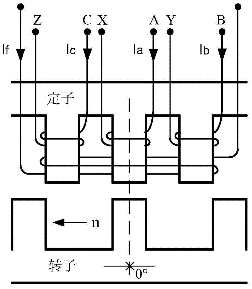
[0070] Such as figure 1 The stator and rotor expansion diagram of the three-phase electric excitation double salient pole motor is shown. The double salient pole motor is electric excitation type, and the excitation winding is placed on the stator, including three stator poles of A phase, B phase and C phase, and the A phase is placed respectively. , B-phase, C-phase armature windings, the excitation current I in the figure f The direction is defined as the positive direction; in the figure, the phase A stator pole and the rotor pole are in the alignment state, and the phase A inductance reaches the maximum value, and the electrical angle at this position is defined as 0°; the rotor rotation direction n in the figure is counterclockwise rotation, and the The direction of rotation is defined as the positive direction.

[0071] Such as fi...


PUM


Abstract

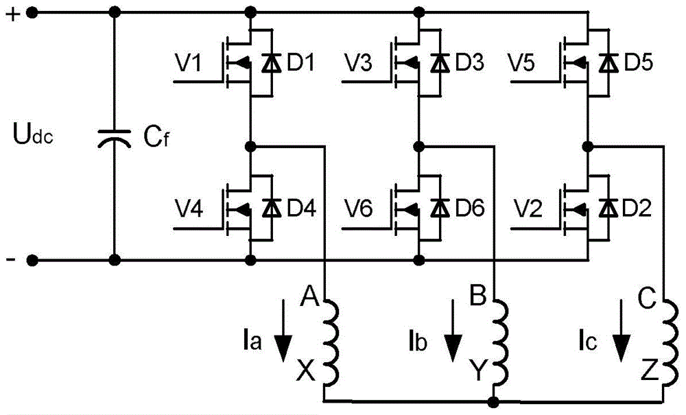
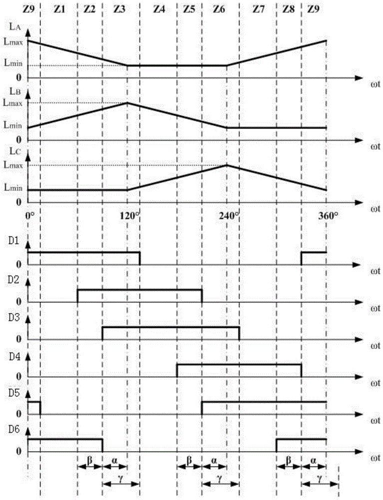
The invention discloses a control method and driving system of a three-phase double-salient-pole brushless direct current motor. According to the control method, after a phase commutation position and a phase current turn-on position of the double-salient-pole motor are advanced, a phase current turn-off position of the double-salient-pole motor is lagged, and three new electrical angle control parameters, namely an advanced phase commutation angle alpha, an advanced turn-on angle beta and a lagged turn-off angle gamma are obtained. A complete electric cycle is divided into nine state sections, each section corresponds to a switching tube conducting modality of a bridge type inverter, the section where a rotor is located is determined according to the position information of the rotor of the double-salient motor, corresponding switching tubes are controlled to be in make and brake state, and the operational control for the motor is achieved. Compared with a traditional double-salient-pole brushless direct current motor control method, by means of the control method and driving system of the three-phase double-salient-pole brushless direct current motor, the output efficiency and working efficiency of the motor driving system can be remarkably improved.

Description

technical field [0001] The invention belongs to the technical field of reluctance synchronous motor drive, and in particular relates to a control method and a drive system of a three-phase double salient pole brushless DC motor. Background technique [0002] Double salient pole motor is a novel type of variable reluctance motor. Both the stator and the rotor have a salient pole structure. There are no windings and permanent magnets on the rotor. It has the advantages of simple structure, low cost, reliable operation, and easy maintenance. It is used in aviation high-speed motors and It has important application value in the field of low-cost and high-efficiency motors on the ground. According to different excitation methods, it can be divided into permanent magnet doubly salient motor, electric excitation doubly salient motor and hybrid excitation doubly salient motor. The permanent magnet double salient pole motor is to place permanent magnets on the motor stator to realiz...

Claims


Application Information

Patent Timeline
Patent Type & Authority Patents(China)
IPC IPC(8): H02P7/28
Inventor 王寅张卓然赵易纬袁琬欣
Owner NANJING UNIV OF AERONAUTICS & ASTRONAUTICS
Learn More