Deep flue gas purification device for efficient desulphurization and dust removal

A flue gas deep purification, desulfurization and dust removal technology, which is applied in the direction of combined devices, chemical instruments and methods, and dispersed particle separation, can solve the problems of increasing the complexity of the flue, high operating costs, and increasing flue gas resistance, so as to achieve saving The effect of construction investment and device operation cost, reduction of investment cost and improvement of effect

Inactive Publication Date: 2015-06-24
YONKER ENVIRONMENTAL PROTECTION
View PDF4 Cites 2 Cited by
  • Summary
  • Abstract
  • Description
  • Claims
  • Application Information

AI Technical Summary

Problems solved by technology

Among them, the double-tower double-circulation process is to connect two absorption towers in series and install a wet electrostatic precipitator behind the second absorption tower. This process has complex flue, large flue gas resistance, large floor space, and high power consumption for operation.
The single-tower double-circulation process is actually a variation of the double-tower double-circulation process, that is, the spray layers of the two towers are superimposed and arranged up and down, and a liquid-receiving tray is set between the spray layers of the tower and the tower to make the spray of the previous absorption tower The shower liquid is not sprayed into the next absorption tower, and the slurry pool of the upper absorption tower is arranged outside the absorption tower. The disadvantage of this process is that the absorption tower is very high, and the wet electrostatic precipitator cannot be installed on it, and the wet electrostatic precipitator can only be horizontal. The layout increases the complexity of the flue, increases the resistance of the flue gas, has two slurry pools, complex operation control, high operating costs, and high investment costs

Method used


Image

  • Deep flue gas purification device for efficient desulphurization and dust removal

Examples


Embodiment Construction

[0016] The present invention will be described in detail below according to the drawings and embodiments.

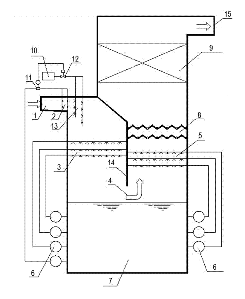
[0017] The flue gas purification device provided in this embodiment includes an absorption tower, a slurry pool 7 and a flue gas absorption area located above the slurry pool 7 are arranged in the absorption tower, a circulating slurry spray device 2 is set at the flue gas inlet 1, and a separator 14 The smoke absorption area is divided into a first absorption area and a second absorption area located on one side of the first absorption area, and a flue gas return channel flowing from the first absorption area to the second absorption area is set between the separator 14 and the slurry pool 7 4. Set the first slurry spray layer 3 in the first absorption zone, set the second slurry spray layer 5 in the second absorption zone, the first slurry spray layer 3, the second slurry spray layer 5 and the circulating slurry spray device 2 Both are connected to the slurry tank 7 th...


PUM


Abstract

The invention relates to a deep flue gas purification device for efficient desulphurization and dust removal. The deep flue gas purification device for efficient desulphurization and dust removal comprises an absorption tower, wherein a slurry pool and a flue gas absorption area located above the slurry pool are arranged in the absorption tower; a circulating slurry spray device is arranged at a flue gas inlet; the flue gas absorption area is partitioned into a first absorption area and a second absorption area located at one side of the first absorption area by a partition plate; a flue gas turn-round channel enabling a flue gas to flow to the second absorption area from the first absorption area is arranged between the partition plate and the slurry pool; the first absorption plate is provided with a first slurry spray layer, and the second absorption area is provided with a second slurry spray layer; the first slurry spray layer, the second slurry spray layer and the circulating slurry spray device are all connected with the slurry pool through a slurry circulation pump; a demister, a dust remover and a flue gas outlet are sequentially arranged above the second slurry spray layer from bottom to top. The device synchronously realizes deep purification in flue gas desulphurization and dust removal in one piece of equipment, thus reducing the height of the absorption tower, reducing the flowing resistance of the flue gas, saving the building expense, and reducing the running cost.

Description

technical field [0001] The invention relates to a flue gas deep purification device for desulfurization and dust removal. Background technique [0002] With the development of my country's economy, environmental pollution is becoming more and more serious, and large-scale haze weather occurs from time to time. In order to improve the environment, at present, more than 80% of international and domestic flue gas desulfurization processes use limestone-gypsum wet desulfurization process, flue gas limestone ——The gypsum wet desulfurization process generally adopts a single absorption tower. With the continuous improvement of environmental protection requirements, the emission limit of pollutants in the flue gas of coal-fired power plants in economically developed areas and some urban agglomerations in my country is required to meet the emission requirements of gas turbine units, that is, The so-called "ultra-clean emission" requires that the NOx concentration in the exhaust flue g...

Claims


Application Information

Patent Timeline
Patent Type & Authority Applications(China)
IPC IPC(8): B01D53/80B01D53/50B01D50/00
Inventor 龚蔚成冯延林谢光辉李蓉姚超良黄黎明
Owner YONKER ENVIRONMENTAL PROTECTION
Why Eureka
Try Eureka