
Steel pusher for pushing steel heating furnace

A technology of heating furnace and steel pusher type, which is applied in the field of material pusher, which can solve the problems of uneven horizontal thrust, high replacement cost of spare parts, corrosion of equipment, etc., achieve good reliability of work, convenient maintenance and operation, and solve the problem of The effect of synchronization problems

Active Publication Date: 2017-04-12
HUATIAN ENG & TECH CORP MCC
View PDF10 Cites 0 Cited by
  • Summary
  • Abstract
  • Description
  • Claims
  • Application Information

AI Technical Summary

Problems solved by technology

[0003] 1. It is greatly affected by the steel billet load in the furnace. Although only one steel is produced at a time, considering the possible adhesion of the billet, the tapping machine may push two or even three billets at the same time, and the disadvantage of the friction pusher is precisely the thrust. Small, in the process of pushing the billet, if the billet is stuck, there will be slippage between the feed roller and the push rod, and the push rod will stop moving forward. It is necessary to increase the power of the motor, increase the clamping pressure of the feed roller, and increase the In the context of promoting energy saving, emission reduction and consumption reduction in the iron and steel metallurgical industry, this design consumes a lot of energy, is cumbersome to debug, has high frequency of replacement of spare parts, and complicated manufacturing process, which is no longer suitable for the requirements of the new era.
[0004] 2. The power source of the traversing mechanism used in the original friction tapping machine is the hydraulic cylinder. There are two hydraulic cylinders to provide the traversing force. One is arranged at the guide groove of the shifting device, and the other is installed under the pinch roller. Through the nylon slide plate installed between the base and the base of the pinch roller device, it is equipped with a dry oil lubrication system to realize the horizontal movement of the equipment; due to the weight difference between the guide groove of the shifting device and the pinch roller device, two sets of hydraulic cylinders act on the equipment The horizontal thrust of the hydraulic cylinder is not uniform, resulting in the speed of the hydraulic cylinder's lateral movement, and the phenomenon of asynchronous displacement is quite obvious. In severe cases, the support bearing between the pinch rollers will be damaged due to excessive lateral force, which will affect production. Rhythm
[0005] 3. The pinch roll pressing and lateral movement functions of the friction tapping machine need to be driven by hydraulic cylinders, and a hydraulic system needs to be independently configured, which increases the power load and enterprise investment
[0006] 4. The stroke control of the original tapping machine adopts the mirror or reflector photoelectric switch, which is difficult to install and adjust and the cost is high; once the signal is lost, the limit will fail and lead to production accidents
[0007] 5. The ejector rod of the friction tapping machine adopts a solid ejector rod without water cooling. Due to the high furnace temperature on the side of the furnace, the ejector rod is easily deformed by heat when it is repeatedly entered and exited in the furnace, and the replacement cost of spare parts is high; some push rods use turbid rings. Water spray cooling, the water consumption is large, and the splashed water droplets are easy to cause corrosion to the equipment at the door of the discharge furnace

Method used


Image

  • Steel pusher for pushing steel heating furnace
  • Steel pusher for pushing steel heating furnace
  • Steel pusher for pushing steel heating furnace

Examples


Embodiment

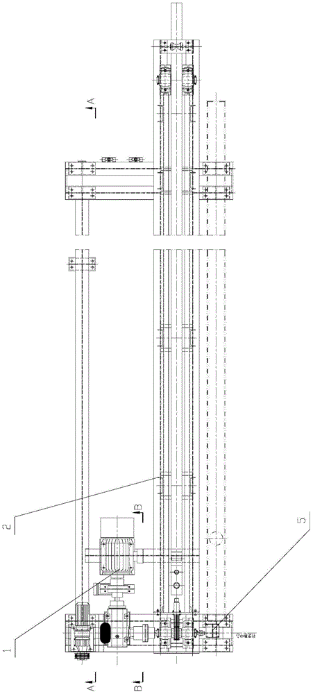
[0028] Such as Figures 1 to 5 As shown, the material pushing machine for the pusher type heating furnace in this embodiment includes a push rod propulsion transmission mechanism 1, a push rod guide frame 2, a traverse trolley 3, a push rod mechanism 4, a stroke control unit 5 and a push rod Water cooling system6. Among them, the ejector rod propulsion transmission mechanism 1 is set on the ejector rod guide frame 2, and the ejector rod mechanism 4 and the ejector rod propulsion transmission mechanism 1 work together to realize the main process functions of the steel pusher; the traverse trolley 3 is assembled with the guide frame 2 , the motor-driven wheeled traversing trolley (3) drives the ejector rod guide frame (2) to realize the horizontal traversing function. The ejector rod water cooling system 6 is connected with the water inlet and outlet in the ejector rod mechanism 4 to realize the cooling function of the ejector rod. The ejector rod mechanism 4 is matched with t...


PUM


Abstract

The invention discloses a novel discharge pusher for pusher-type heating furnaces. The novel discharge pusher for pusher-type heating furnaces comprises an ejector rob mechanism, an ejector rob guide rack and an ejector rob propulsion drive mechanism, wherein the ejector rob propulsion drive mechanism is arranged on the ejector rob guide rack, the ejector rob propulsion drive mechanism comprises a fixed seat and an adjusting bracket, the adjusting bracket supports the fixed seat, the fixed seat is provided with a chain drive device for driving the ejector rob mechanism, the chain drive device comprises a motor, a speed reducer and a chain wheel, the chain wheel is connected with the speed reducer, the chain wheel is provided with a chain, and the motor and the speed reducer drive the ejector rob mechanism to carry out forward and backward reciprocating movement in the ejector rob guide rack through the chain wheel and the chain. The invention provides the novel discharge pusher for pusher-type heating furnaces, which is simple in structure, low in failure rate, economic and practical.

Description

technical field [0001] The invention relates to a discharging steel pushing machine, in particular to a discharging steel pushing machine used for a steel pushing type heating furnace. Background technique [0002] The pusher type end-in and side-out continuous heating furnace relies on the charging pusher and the discharge pusher to complete the task of transporting materials in the furnace. The tapping machine is the key tapping equipment of the heating furnace, which is responsible for the billet after heating Push out one by one from the heating furnace to the roller table of the furnace. Usually, friction wheel tappers are used in similar projects. The push rod is driven by the friction of the pinch roller to promote the technological process of the production of the steel billet from the furnace. By analogy, the steel machine has exposed the following disadvantages in the course of engineering practice: [0003] 1. It is greatly affected by the steel billet load in th...

Claims


Application Information

Patent Timeline
Patent Type & Authority Patents(China)
IPC IPC(8): C21D9/70
Inventor 张翼
Owner HUATIAN ENG & TECH CORP MCC
Learn More