Technological manufacturing method of atmospheric burner

A production method and burner technology, which are applied in combustion methods, burner manufacturing, gas fuel burners, etc., can solve the problems of large gas resistance, poor air tightness, and the tendency of backfire, so as to reduce the gas pressure loss and improve the Combustion efficiency, effect of reducing tempering tendency

Inactive Publication Date: 2015-06-24
SHANGHAI OTT ELECTRICAL
View PDF6 Cites 1 Cited by
  • Summary
  • Abstract
  • Description
  • Claims
  • Application Information

AI Technical Summary

Problems solved by technology

The various parts of the existing atmospheric burner are mostly made by traditional casting process. However, due to the limitation of traditional casting process, the inner cavity wall of the cast burner is relatively rough, resulting in the presence of gas when the gas flows in the inner cavity. Larger resistance, so it is not conducive to the introduction of primary air, making the combustion efficiency lower
In addition, in the existing split-type design of the burner head, there is a certain gap between the split body and the body, resulting in poor air tightness, so that the flame hole can be obtained when using gas that burns faster or has a lower pressure. The gas flow rate is low and there is a tendency to flash back

Method used


Image

  • Technological manufacturing method of atmospheric burner
  • Technological manufacturing method of atmospheric burner
  • Technological manufacturing method of atmospheric burner

Examples


Embodiment Construction

[0024] The present invention will be further described below in conjunction with the accompanying drawings.

[0025] Compared with the traditional manufacturing process, the present invention is different in that it comprises the following steps:

[0026] Step S1: casting the burner head by casting iron or brass;

[0027] Step S2: Grinding the inner wall of the burner head to remove the uneven parts left by casting;

[0028] Step S3: using a stainless steel tube with a smooth inner wall to make the injection tube;

[0029] Step S4: making the burner cavity from a stainless steel plate with a smooth surface by mold stretching;

[0030] Step S5: Welding or riveting the polished burner head and the burner cavity together to seal the interface;

[0031] Step S6: Welding or riveting the injector tube and the burner cavity to seal the interface.

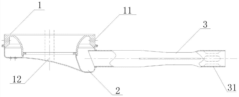
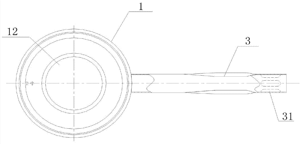
[0032] Such as figure 1 As shown, the present invention is made up of three parts of injection tube 3, burner cavity 2 and burner he...


PUM

PropertyMeasurementUnit
surface roughnessaaaaaaaaaa

Abstract

The invention discloses a technological manufacturing method of an atmospheric burner. The atmospheric burner comprises an injection pipe, a burner cavity and a burner head. According to the method, a cast iron or brass casting method is adopted for casting the burner head; the inner wall of the burner head is polished; the injection pipe is made of a stainless steel pipe with a smooth inner wall; a stainless steel plate with a smooth surface is made into the burner cavity; the polished burner head and the burner cavity are welded or riveted together, and the injection pipe and the burner cavity are welded or riveted together. Compared with burner obtained through a traditional technology, the atmospheric burner is small in gas flowing resistance and high in burning efficiency. Moreover, the burner head with vent holes and the burner cavity are connected, so that sealing performance is better, gas pressure loss is lowered except for fire holes, under the condition that gas burns quickly or the pressure of gas is low, the fire holes still can have high gas flow rate, and the backfire tendency is reduced.

Description

technical field [0001] The invention relates to an atmospheric burner, in particular to a manufacturing method of the atmospheric burner. Background technique [0002] Atmospheric burners are widely used in metallurgy, chemical industry and other industries, and are usually composed of three parts: ejector tube, burner cavity and burner head. The various parts of the existing atmospheric burner are mostly made by traditional casting process. However, due to the limitation of traditional casting process, the inner cavity wall of the cast burner is relatively rough, resulting in the presence of gas when the gas flows in the inner cavity. Larger resistance, so it is not conducive to the introduction of primary air, so that the combustion efficiency is lower. In addition, in the existing split-type design of the burner head, there is a certain gap between the split body and the body, resulting in poor air tightness, so that the flame hole can be obtained when using gas that bur...

Claims


Application Information

Patent Timeline
Patent Type & Authority Applications(China)
IPC IPC(8): F23D14/04F23D14/46
CPCF23D14/04F23D2213/00
Inventor 杜仁尧李卫东
Owner SHANGHAI OTT ELECTRICAL
Why Eureka
Try Eureka