

Five-nozzle combustor structure applied to gas turbine low-pollution combustion chamber
A technology of nozzle burners and gas turbines, which is applied in the direction of combustion chambers, continuous combustion chambers, combustion methods, etc., and can solve the problems of high NOx emissions and long residence time
Active Publication Date: 2015-06-24
SHANGHAI JIAO TONG UNIV
View PDF12 Cites 21 Cited by
- Summary
- Abstract
- Description
- Claims
- Application Information
AI Technical Summary
Problems solved by technology
However, there is a long residence time of high-temperature reactants in the combustion chamber, resulting in higher NOx emissions
Method used
View moreImage
Smart ImageViewing Examples

Examples
Embodiment
[0026] Figure 6 It is a schematic diagram of the combustion chamber arrangement of a five-nozzle burner. As shown in the figure, in the specific arrangement, the five-nozzle combustor can be arranged as a tubular combustion chamber or an annular tubular combustion chamber according to the structure of the actual gas turbine.
Login to View More PUM
 Abstract
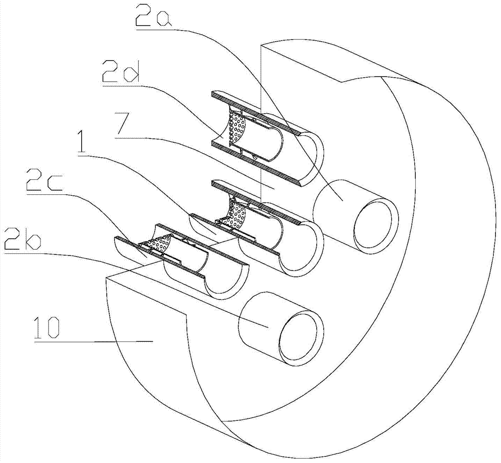
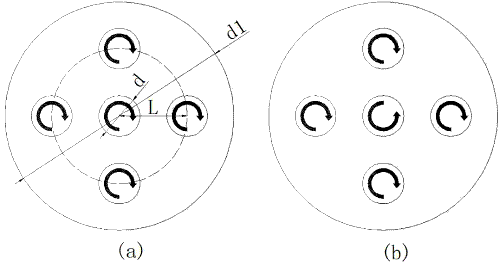
The invention discloses a five-nozzle combustor structure applied to a gas turbine low-pollution combustion chamber, the combustor is composed of five low-swirl nozzles, the surrounding nozzles are arranged evenly at equal intervals in the circumferential direction along the central nozzle, and the swirling flow directions of the surrounding nozzles are the same. The swirling flow direction of the central nozzle is the same as or opposite to the swirling flow directions of the surrounding nozzles. Lean premixed combustion of gas fuel and air is adopted, the flame residence time is reduced, the flame temperature is reduced, and the aim of low emission is achieved. The five-nozzle combustor structure applied to the gas turbine low-pollution combustion chamber has the advantages of being stable in combustion, low in emission, low in noise, reasonable in design, simple in structure, and suitable for the gas turbine low-pollution combustion chamber.
Description
technical field [0001] The invention relates to the technical field of gas turbines, in particular to a five-nozzle burner structure suitable for low-pollution combustion chambers of gas turbines. Background technique [0002] The swirl stable combustion technology is widely used in gas turbine combustors. Traditional high-swirl burners use the recirculation zone created by the swirl to speed up the mixing of high-temperature combustion products with fresh reactants, thereby stabilizing the flame. However, there is a long residence time of high-temperature reactants in the combustion chamber, resulting in higher NOx emissions. Low-swirl combustion refers to maintaining stable flame combustion with a low swirl number (the swirl number is generally between 0.4 and 0.55). Compared with high-swirl combustion, there is no severe backflow zone in the low-swirl flow field , the streamline expands at the exit of the nozzle, resulting in a decrease in air velocity, and the flame st...
Claims
Login to View More Application Information
Patent Timeline
 Patent Type & AuthorityApplications(China)
IPC IPC(8): F23R3/38
Inventor柳伟杰葛冰臧述升
OwnerSHANGHAI JIAO TONG UNIV