Synthetic aperture radar residual range migration correction method

A synthetic aperture radar and range migration correction technology, which is applied in the radar field and can solve the problems of reduced processing efficiency, large amount of computation, poor estimation accuracy of residual range migration, etc.

Active Publication Date: 2015-06-24
UNIV OF ELECTRONICS SCI & TECH OF CHINA
View PDF3 Cites 10 Cited by
  • Summary
  • Abstract
  • Description
  • Claims
  • Application Information

AI Technical Summary

Problems solved by technology

However, this method is carried out on the premise of reducing the resolution in the range direction, and the estimation accuracy of the residual range migration is usually poor
The document "D.Zhu,"SAR signal based motion compensation through combining PGA and 2-D map drift,"Conference on 2nd Asian-Pacific Synthetic Aperture Radar.pp.435-438,2009" divides the data into azimuth blocks, when The azimuth sampling point of each piece of data is small enough, and the residual distance migration within each piece of data can be ignored. Then, the distance sub-view correlation method is used to move each piece of data to the same distance resolution unit. However, the data block operation greatly reduces the processing efficiency.
The document "Gonzalez-Partida J-T, Almorox-Gonzalez P, Burgos-Garcia M, Dorta-Naranjo B-P, SAR System for UAV Operation with Motion Error Compensation beyond the Resolution Cell. Sensors.2008; 8(5):3384-3405" adopts The envelope alignment method in Inverse Synthetic Aperture Radar (ISAR) corrects the residual range migration in the time domain, and corrects the migration trajectory to the same range unit through interpolation processing. However, the interpolation processing requires a large amount of calculation and reduces the processing efficiency.

Method used


Image

  • Synthetic aperture radar residual range migration correction method
  • Synthetic aperture radar residual range migration correction method
  • Synthetic aperture radar residual range migration correction method

Examples


Embodiment Construction

[0072] The technical solutions of the present invention will be further described below in conjunction with the drawings and specific embodiments.

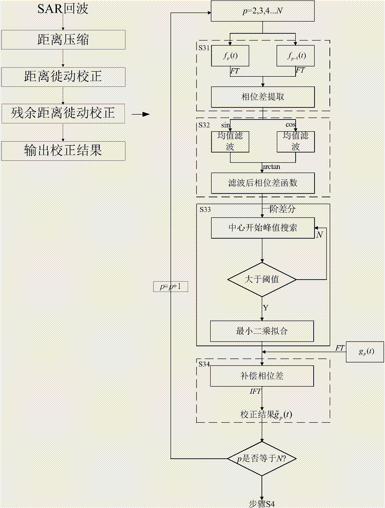
[0073] Such as figure 1 As shown, a synthetic aperture radar residual range migration correction method includes the following steps:

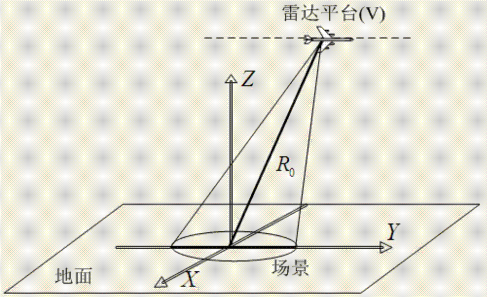
[0074] S1. Obtain the two-dimensional echo signal, and use the conventional matched filtering method for range pulse compression; the geometric configuration of the synthetic aperture radar is shown as figure 2 As shown, the parameters required for the simulation are shown in Table 1. Set the historical deviation of the radar platform distance ΔR(t) caused by the motion error to 2.4cos(2π·t·2.5) (t is the azimuth time, the range of change is [-0.425,0.425] seconds, where t=0 second is the beam The time the center illuminates the target).

[0075] Table 1 System parameter table

[0076]

[0077] Step S1 specifically includes the following sub-steps:

[0078] S11. Calculate the distance history of the rad...


PUM


Abstract

The invention discloses a synthetic aperture radar residual range migration correction method. The method includes the following steps of firstly, obtaining two-dimensional echo signals, and conducting range-direction pulse compression through a conventional matched filtering method; secondly, conducting range migration correction on two-dimensional echo data obtained after the range-direction pulse compression is conducted; thirdly, conducting residual migration correction on the two-dimensional echo data where range migration correction is conducted, wherein the echo signals where the range migration correction is conducted are mocked up, the residual range migration correction is sequentially conducted on the pth line of azimuth data of the signals which are mocked up, p is larger than or equal to 2 and smaller than or equal to N, and N is the range-direction sampling number; fourthly, outputting a correction result. In the calculation process, no interpolation needs to be conducted, the data operation amount can be decreased, and the processing efficiency can be improved; under the data segmentation condition, the displacement amount of a staggered image in the space can be accurately estimated and corrected, the correction accuracy can reach the sub pixel level, and accurate and reliable data are provided for the subsequent high-accuracy imaging.

Description

Technical field [0001] The invention belongs to the field of radar technology, and particularly relates to a method for correcting residual range migration of synthetic aperture radar. Background technique [0002] Synthetic Aperture Radar (SAR) is an all-weather, all-weather two-dimensional high-resolution microwave remote sensing imaging radar. It has been widely used in the fields of earth remote sensing, resource exploration, reconnaissance, surveying and mapping, and disaster forecasting. The high resolution of the SAR range is obtained by transmitting a chirp signal with a large time-wide bandwidth product, and the high resolution of the azimuth is obtained by the Doppler effect produced by the relative movement between the radar and the target. The relative movement between the radar and the target, on the one hand, brings about the phase change in the azimuth direction; on the other hand, the echo delay of the same point target at different azimuth times is different, tha...

Claims


Application Information

Patent Timeline
Patent Type & Authority Applications(China)
IPC IPC(8): G01S7/40
CPCG01S7/40
Inventor 杨建宇蒲巍李文超黄钰林武俊杰李中余杨海光
Owner UNIV OF ELECTRONICS SCI & TECH OF CHINA
Why Eureka
Try Eureka