
Narrow pulse driving circuit

A driving circuit and narrow pulse technology, applied in circuits, electrical components, laser parts, etc., can solve the problems of large driving device, easy to be affected by parasitic parameters, undershoot of pulse current signal, etc., to achieve miniaturization, improve The effect of parameter control accuracy

Inactive Publication Date: 2015-06-24
INST OF MICROELECTRONICS CHINESE ACAD OF SCI
View PDF7 Cites 11 Cited by
  • Summary
  • Abstract
  • Description
  • Claims
  • Application Information

AI Technical Summary

Problems solved by technology

For example, the shortest pulse of the QCL driver of AlpesLasers in Switzerland is 22ns, and due to the use of PWM driving technology, there is no current feedback mechanism, it is easily affected by parasitic parameters, and the stability is poor
Although the products of ILX Lightwave in the United States adopt the combination of constant current drive mode and PWM drive technology, the shortest pulse reaches 25ns, and the pulse current signal is seriously undershooted.
In addition, the drive units offered by these companies are very large and suitable only for laboratory applications, not as portable applications for pulsed lasers

Method used

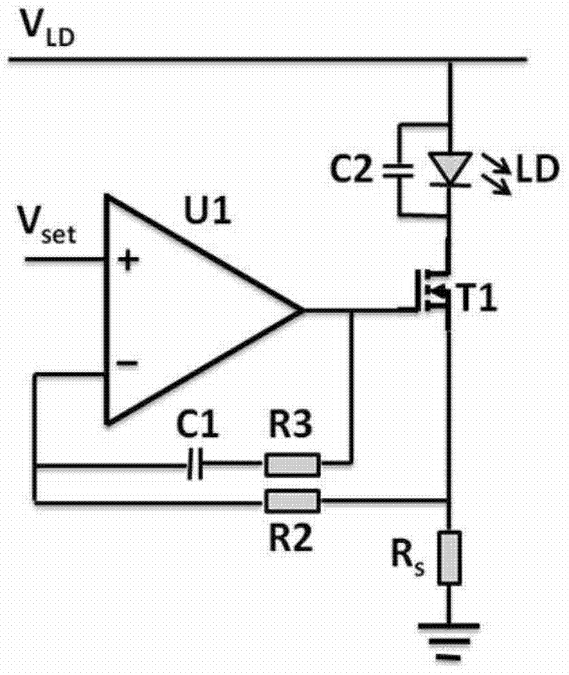
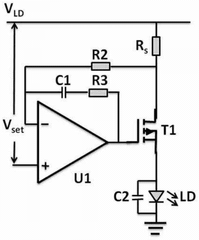
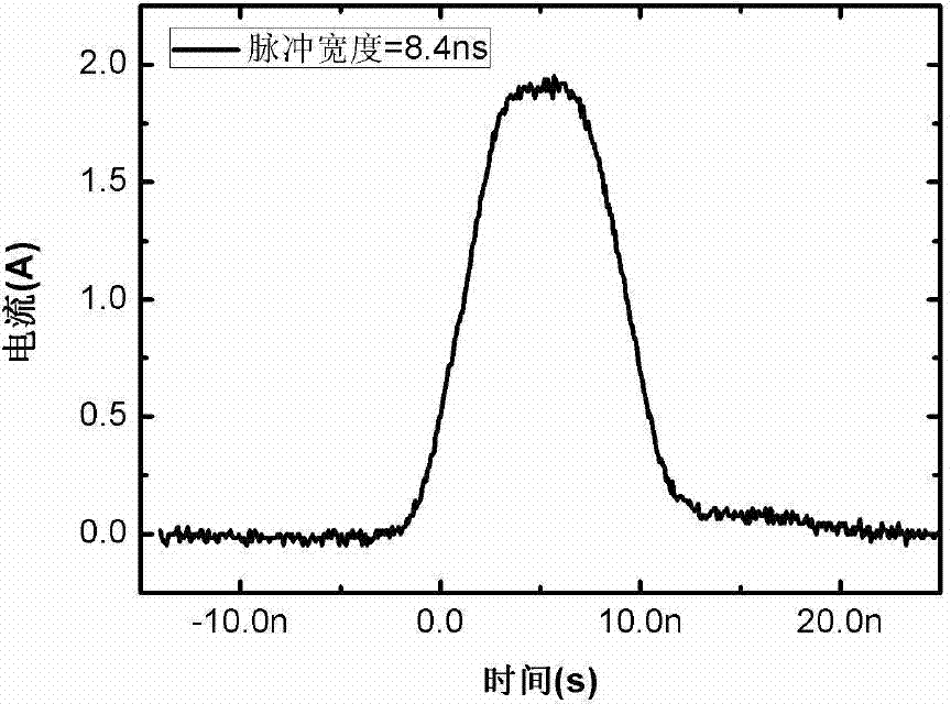

Image

  • Narrow pulse driving circuit
  • Narrow pulse driving circuit
  • Narrow pulse driving circuit

Examples


Embodiment Construction

[0027] The features and technical effects of the technical solution of the present invention will be described in detail below with reference to the accompanying drawings and in combination with schematic embodiments, and a narrow pulse drive circuit that strictly controls the pulse constant current on the load to improve the accuracy of parameter control is disclosed. . It should be pointed out that similar reference numerals represent similar structures, and the terms "first", "second", "upper", "lower" and the like used in this application can be used to modify various device structures or manufacturing processes . These modifications do not imply spatial, sequential or hierarchical relationships of the modified device structures or fabrication processes unless specifically stated.

[0028] According to an embodiment of the present invention, a driving circuit is provided, which converts an input pulse signal into a precisely controllable pulse current signal. The technol...


PUM


Abstract

A narrow pulse driving circuit comprises a load, a control pipe, a first resistor and an operational amplifier. The load and the control pipe are connected in series between a power supply voltage end and a grounding end in positive sequence and / or negative sequence. The first resistor is used as a sampling resistor. The output end of the operational amplifier is connected to a control end of the control pipe. The positive phase input end of the operational amplifier is connected with input control voltage. The negative phase input end of the operational amplifier is connected to a node between the control pipe and the first resistor through a second resistor. According to the narrow pulse driving circuit, input pulse voltage signals are converted into pulse current signals, the load is subjected to strict pulse constant-current control, and semiconductor laser device parameter control accuracy is improved.

Description

technical field [0001] The invention relates to the field of laser, gas sensor and circuit design, in particular to a pulse laser drive circuit device. Background technique [0002] Due to its small size, high power, and output wavelengths covering infrared bands, pulsed lasers have attracted widespread attention and applications. It has a wide range of applications in many fields such as gas sensors, medical equipment, national defense security, food safety, industrial monitoring and environmental detection. In recent years, with the successful development of many pulsed lasers in the mid-infrared band, the related reports based on pulsed laser experiments and applications are increasing, which has become a research hotspot. However, such pulsed lasers are usually expensive and prone to failure under high pulse or high current, which limits the commercial application of pulsed lasers. [0003] In addition, in the application of laser absorption spectroscopy detection, the...

Claims


Application Information

Patent Timeline
Patent Type & Authority Applications(China)
IPC IPC(8): H01S5/042
Inventor 余兆安刘明
Owner INST OF MICROELECTRONICS CHINESE ACAD OF SCI
Learn More