External cavity widely tunable laser using a silicon resonator and micromechanically adjustable coupling

a silicon resonator and external cavity technology, applied in the direction of laser details, laser optical resonator construction, optical resonator shape and construction, etc., can solve the problems of low chip yield, large chip size, and low manufacturing cost, and achieve low cost, wide tunable

Inactive Publication Date: 2014-12-09
T&S COMM
View PDF9 Cites 15 Cited by
  • Summary
  • Abstract
  • Description
  • Claims
  • Application Information

AI Technical Summary

Benefits of technology

[0007]Some aspects of the present invention provide a laser source that is widely tunable, simple to manufacture, and low cost.
[0012]Some aspects of this invention provide a laser source that has optical properties suitable for long distance single mode fiber optic communications. This includes high sidemode suppression ratio, high optical power, narrow linewidth, and low electrical power consumption.
[0016]In addition to the lens, the silicon filter could also incorporate a grating coupler, such that the lens can precisely adjust the angle of the beam for maximum coupling of the light into the grating coupler and therefore into the waveguide of the silicon filter.

Problems solved by technology

Currently there are three main approaches to making a tunable laser for fiber optic network applications, each of which has some limitations in cost and complexity of manufacture.
Since all these sections require different geometries and must be carefully matched for proper operation, the chip yield can be low.
Furthermore, with all these different elements, the chip size can be quite large, which in the expensive InGaAsP material system, also translates to higher cost.
In this case the chip cost is low, but relatively expensive other components are needed and all the parts have to be carefully aligned.
Here the complexity of the switch and the need to make many different lasers increases the cost and complexity.
The issue is that these rings can be difficult to make in the InGaAsP material and they generally have very small optical modes that is generally incompatible with the mode in the gain section.
However, optical coupling between the ring resonators fabricated in silicon with a very small optical mode and the InGaAsP gain chip with the much larger optical mode has been challenging.
The high loss of the coupling has so far translated to poor performance.

Method used


Image

  • External cavity widely tunable laser using a silicon resonator and micromechanically adjustable coupling
  • External cavity widely tunable laser using a silicon resonator and micromechanically adjustable coupling
  • External cavity widely tunable laser using a silicon resonator and micromechanically adjustable coupling

Examples


Embodiment Construction

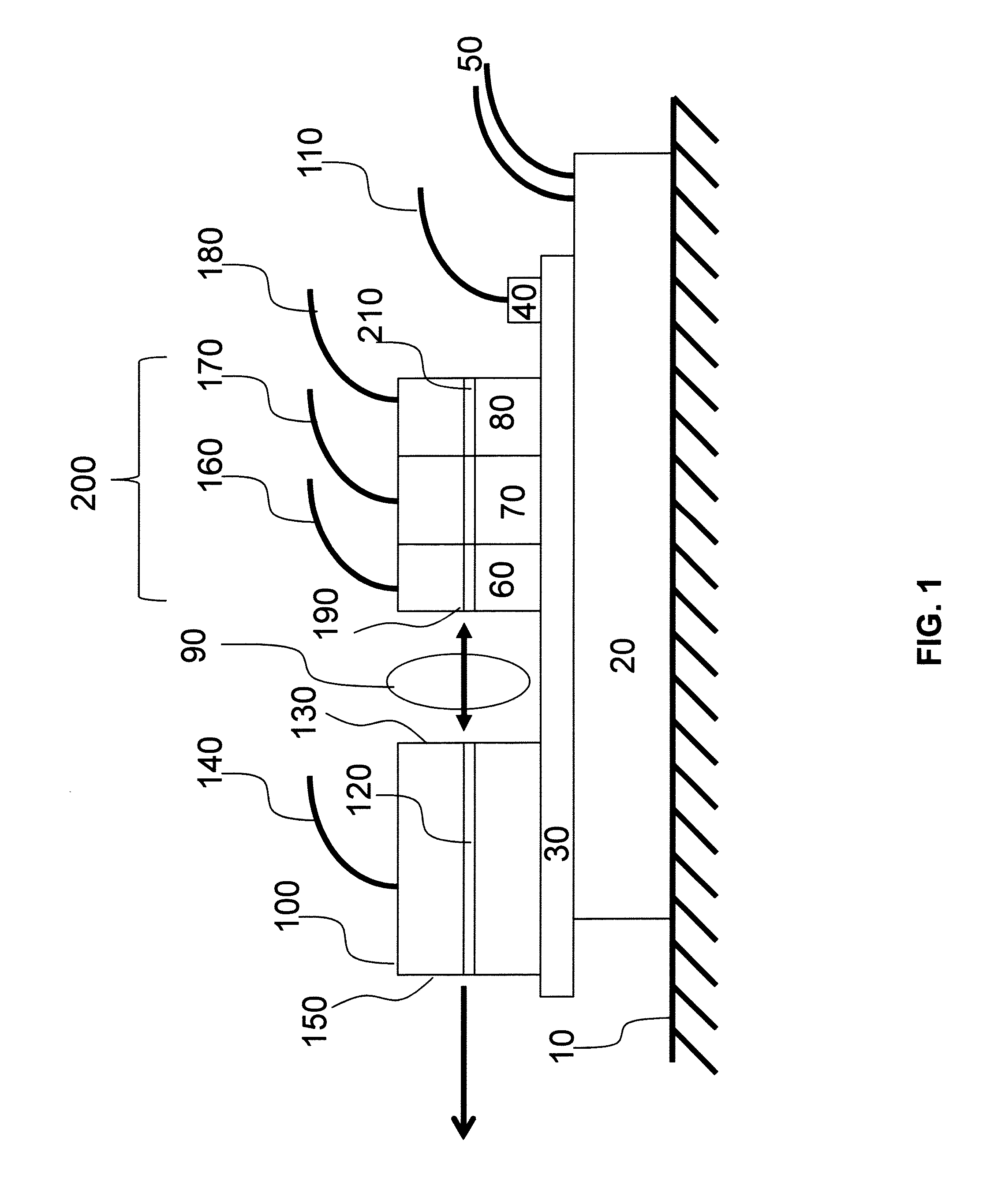
[0034]FIG. 1 schematically illustrates a simple embodiment of the invention. A heatsink 10 is connected thermally to the environment and provides cooling for a module. The module itself is temperature controlled using a thermoelectric cooler 20 which is connected to the heatsink 10. A thermistor 40 monitors the temperature of a carrier 30 coupled to the thermoelectric cooler. If the temperature becomes higher than the desired temperature, current is supplied through wires 50 to the thermoelectric cooler 20 such that heat is removed from the carrier 30. If the carrier 30 becomes too cool, the current to the thermoelectric cooler is either reduced or reversed in direction such that the temperature of the carrier 30 and the topical components mounted on the carrier are generally constant. The temperature reading of the thermistor is monitored by measuring its electrical resistance using wire 110.

[0035]An external cavity laser assembly is bonded to the temperature controlled carrier 30 ...


PUM


Abstract

A widely tunable laser is described where a compound semiconductor gain chip is coupled to a waveguide filter fabricated on silicon. The filter has two resonators with different free-spectral-ranges, such that Vernier tuning between the filters can be used to provide a single wavelength of light feedback into the gain chip, where the wavelength is adjustable over a wide range. The coupling between the gain chip and the filter is realized through a microlens whose position can be adjusted using micromechanics and locked in place.

Description

CROSS REFERENCE TO RELATED APPLICATIONS[0001]This application claims the benefit of the filing date of U.S. Provisional Patent Application No. 61 / 436,904, filed Jan. 27, 2011, the disclosure of which is incorporated by reference.BACKGROUND OF THE INVENTION[0002]The present invention relates to telecommunication laser devices in general, and more particularly to external cavity lasers with separate gain and filter sections that can provide broad wavelength tunability.[0003]Much of fiber optic telecommunications uses multiple wavelength channels in the same fiber. Having multiple lanes in the same fiber increases the bandwidth capacity and allows rerouting or adjustment of the network by adding or dropping channels from one fiber to the next. To eliminate inventory and logistical issues of producing and servicing of dozens of lasers of different wavelengths, tunable lasers are now generally used in fiber optic networks. A single laser can provide any one of the channels needed and is ...

Claims


Application Information

Patent Timeline
Patent Type & Authority Patents(United States)
IPC IPC(8): H01S5/022H01S5/14H01S5/026H01S5/10H01S3/10H01S5/024H01S5/00
CPCH01S5/142H01S5/02284H01S5/0071H01S5/1032H01S5/02248H01S5/0261H01S5/02415H01S5/02288H01S5/02251H01S5/02253H01S5/02325
Inventor YOFFE, GIDEONHEANUE, JOHNPEZESHKI, BARDIA
Owner T&S COMM
Why Eureka
Try Eureka