Heart generating system

A power generation system and heart technology, applied in the field of medical devices, can solve the problems of large volume, complex structure, affecting heart function, etc., and achieve the effect of small volume

Inactive Publication Date: 2015-07-01
SECOND MILITARY MEDICAL UNIV OF THE PEOPLES LIBERATION ARMY
View PDF4 Cites 6 Cited by
  • Summary
  • Abstract
  • Description
  • Claims
  • Application Information

AI Technical Summary

Problems solved by technology

[0004] However, since the heart is the "engine" of the human body, improper collection of cardiac kinetic energy will inevitably affect the function of the heart and even cause heart damage
In addition, traditional electromagnetic induction generators based on Faraday's law are large in size and complex in structure, and are not suitable for implantation in the body.

Method used


Image

  • Heart generating system
  • Heart generating system
  • Heart generating system

Examples


Embodiment 1

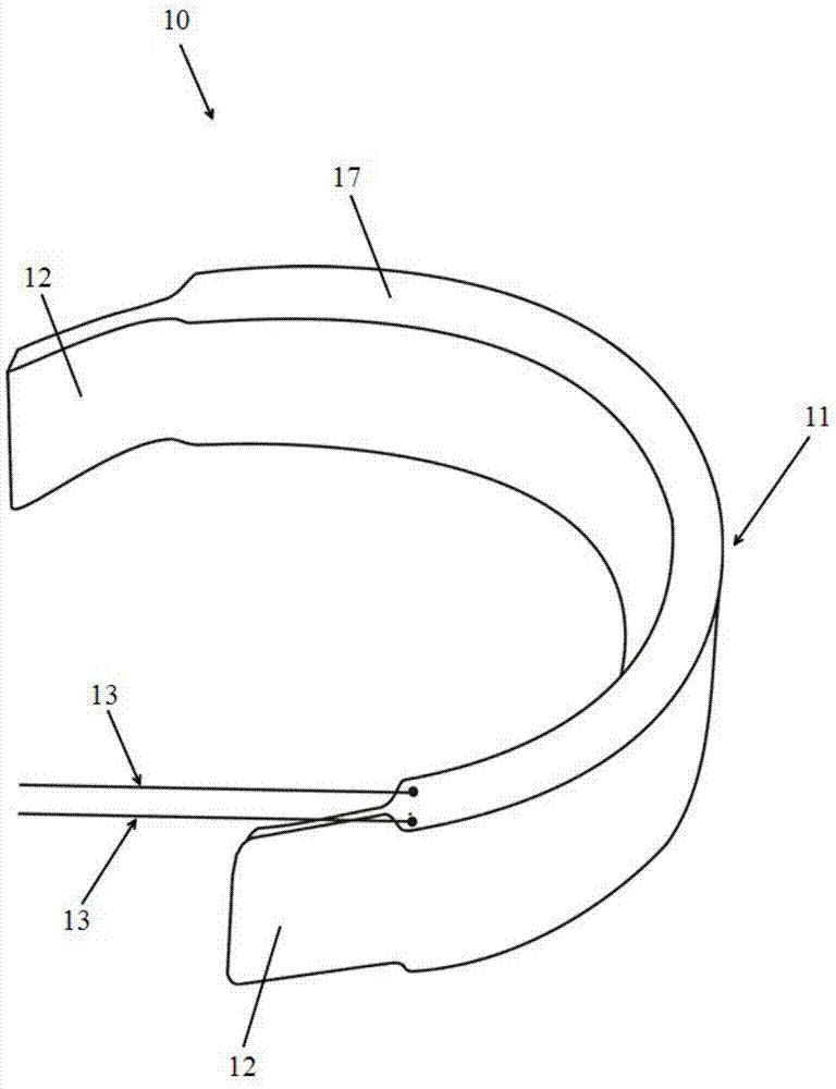
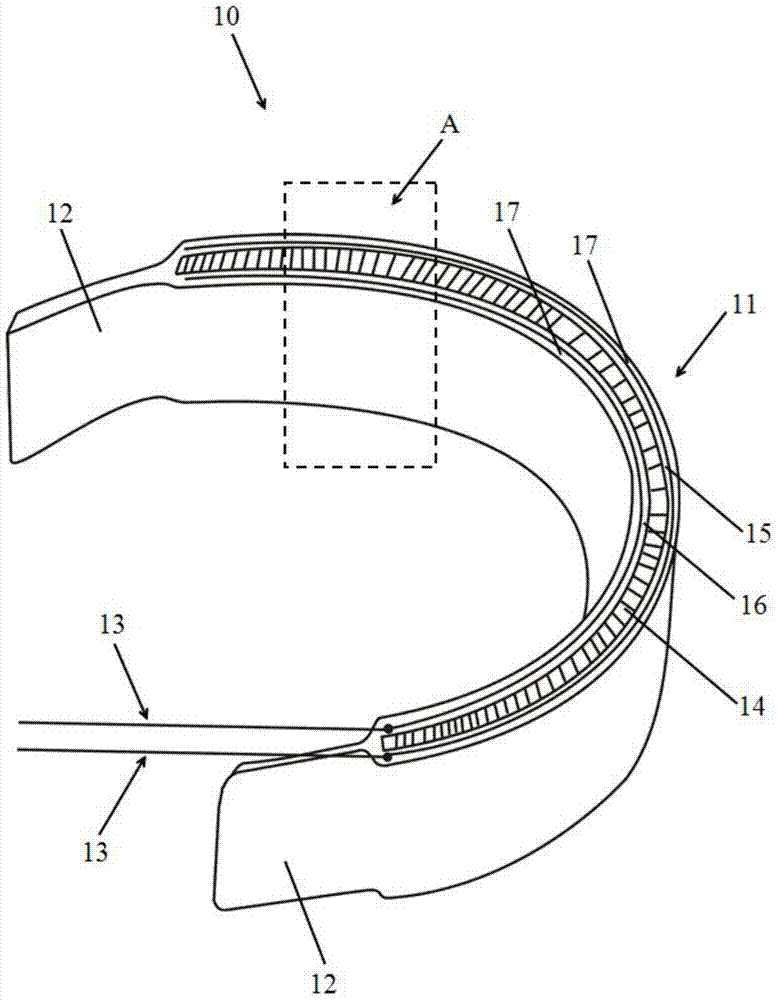
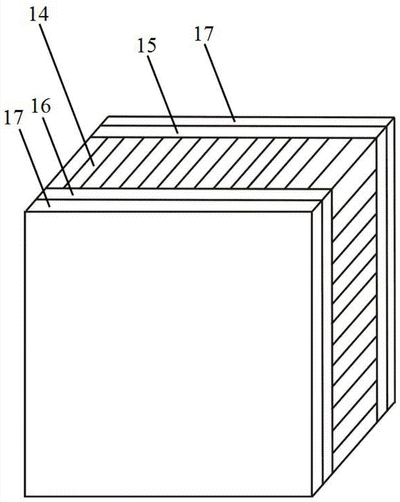
[0033] figure 1 is a structural schematic diagram of the cardiac power generation system of the present invention, figure 2 is a cross-sectional view of the cardiac power generation system of the present invention, image 3 yes figure 2 Partial enlarged view of region A of the cardiac power generation system in . Such as figure 1 , figure 2 and image 3 As shown, the heart power generation system 10 includes a power generation body 11 , an adjustment terminal 12 and an output electrode 13 . Wherein, the power generating body 11 is a multi-layer film structure, including a piezoelectric material layer 14 located in the center layer of the main body, and a first electrode layer 15 and a second electrode layer 16 respectively located on both sides of the piezoelectric material layer 14 . The encapsulation layer 17 is a biocompatible flexible polymer insulating material covering the surface of the power generation body 11 and the output electrode 13 . The encapsulation la...

Embodiment 2

[0043] In this embodiment, the shape of the power generating body and the arrangement of the adjusting end are the same as in Embodiment 1, the difference is that in this embodiment, the power generating layer of the center layer of the main body is made of nanoscale piezoelectric ceramic material.

[0044]During the implantation process, a pressure sensor is placed between the power generating body 11 and the aortic wall to detect the real-time pressure, so as to ensure that the pressure of the power generating body 11 on the aortic wall is less than 140mmHg.

[0045] Another difference is that in this embodiment, the adjusting end 12 is fixed by a titanium clip.

Embodiment 3

[0047] In this embodiment, the shape of the power generating body and the setting of the adjustment end are the same as in Embodiment 1, the difference is that in this embodiment, the piezoelectric material layer of the central layer of the main body is made of piezoelectric polymer, and the adjustment end is made of adhesive Fix by gluing.


PUM


Abstract

The invention provides a heart nano generating system. The system is characterized by comprising a generating body, an output part, a fixing part and a packaging layer, wherein the generating body is of a multi-layer film structure, comprising a piezoelectric material layer in the center of the generating body, an electrode layers positioned at two sides of the piezoelectric material layer; the generating body is attached on the surface of heart to acquire heart energy so as to generate electricity energy; the fixing part is positioned at the side edge of the generating body and used for fixing the generating body to epicardium; the packing layer covers the surfaces of the generating body, the output part and the fixing part; the output part is connected with the electrode layer and used for conveying the electricity energy produced by the generating body to an implantable electronic device. According to the system, the electricity energy can be continuously produced as heart beats, so that the power can be continuously supplied to the implantable electronic device, a battery used as a power supply can be saved, and as a result, the problem of replacing the battery for operation after the power of the battery runs out can be solved.

Description

technical field [0001] The invention relates to a cardiac power generation system, which belongs to the field of medical equipment. Background technique [0002] With the development of medical technology, more and more diseases can be treated by implanted medical electronic devices in the body. However, until now, medical electronic devices put into clinical applications all require batteries as a source of electrical energy. For medical electronic devices implanted in the body, once the battery energy is exhausted, the battery needs to be replaced by surgical operation. This will not only cause physical and mental pain to patients, but also increase the financial burden on patients and their families. [0003] Inside the human body, both the contraction of the heart and the flow of blood have steady and uninterrupted kinetic energy. If a small portion of this kinetic energy can be harvested and converted into electricity, it is expected to power a variety of implantable...

Claims


Application Information

Patent Timeline
IPC IPC(8): A61N1/378H02N2/18
Inventor 张浩曲丹
Owner SECOND MILITARY MEDICAL UNIV OF THE PEOPLES LIBERATION ARMY
Why Eureka
Try Eureka