Reaction chamber and plasma processing equipment

A reaction chamber and plasma technology, applied in the direction of plasma, metal material coating process, gaseous chemical plating, etc., can solve the problems of process influence and process stability, etc. Effect

Active Publication Date: 2015-07-01
BEIJING NAURA MICROELECTRONICS EQUIP CO LTD
View PDF5 Cites 8 Cited by
  • Summary
  • Abstract
  • Description
  • Claims
  • Application Information

AI Technical Summary

Problems solved by technology

[0005] However, the use of the above-mentioned reaction chamber 10 inevitably has the following problems in practical applications, that is, during the process, a metal film is often deposited at the connection between the slit 15 and the upper surface of the insulating ring 17, which will make the Faraday shield The connection between the slit 15 of 14 and the insulating ring 17 is connected with the Faraday shield 14, thereby forming a conductive path, and the induction coil 11 will generate an induced current in the conductive path, thereby causing an impact on the process in the reaction chamber, and then Affect the stability of the process in the reaction chamber

Method used


Image

  • Reaction chamber and plasma processing equipment
  • Reaction chamber and plasma processing equipment
  • Reaction chamber and plasma processing equipment

Examples


Embodiment Construction

[0029] In order for those skilled in the art to better understand the technical solution of the present invention, the reaction chamber and the plasma processing equipment provided by the present invention will be described in detail below with reference to the accompanying drawings.

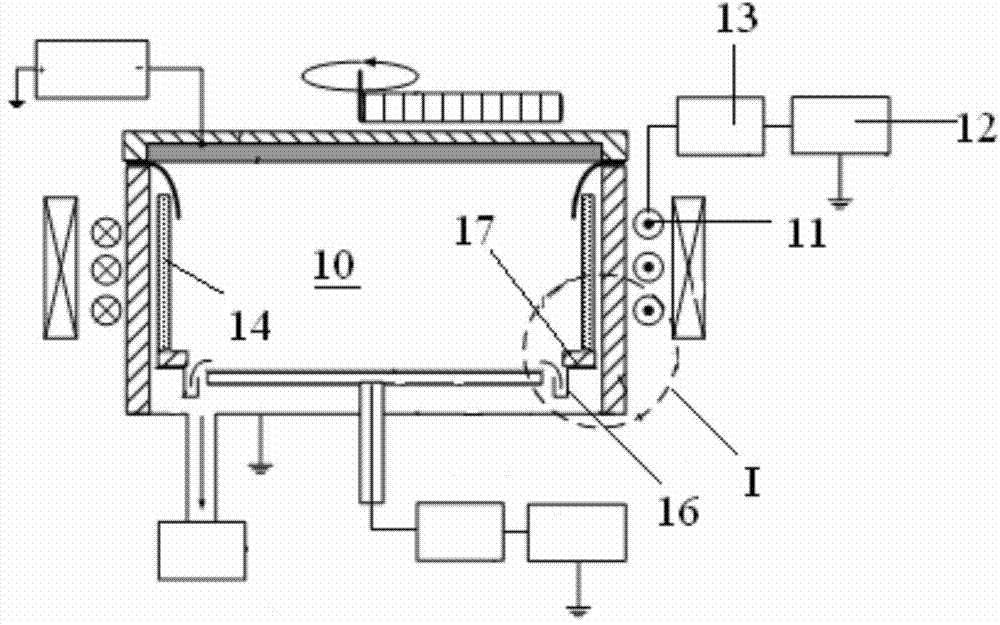
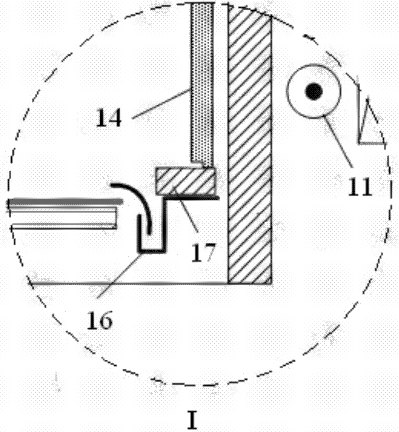
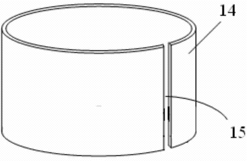
[0030] Figure 4 Schematic diagram of the structure of the reaction chamber provided by the first embodiment of the present invention. Figure 5 for Figure 4 Schematic diagram of the structure of the Faraday shield, insulating ring and shielding ring in the middle. Please also refer to Figure 4 and Figure 5 The reaction chamber 20 provided in this embodiment includes a Faraday shield 21 sleeved inside the side wall of the reaction chamber 20, an insulating ring 22, a shielding ring 23 made of a non-magnetic metal material, an induction coil 24 and A radio frequency power supply 25 electrically connected thereto. Wherein, the Faraday shield 21 is stacked on the insulating ring 22, at leas...


PUM


Abstract

The invention provides a reaction chamber and plasma processing equipment. The reaction chamber comprises a Faraday shield sleeving the inner side of the side wall of the reaction chamber, an insulating ring and a shielding ring made from a non-magnetic conductive metal material, wherein the Faraday shield is overlapped on the insulating ring, at least one seam is arranged along the circumferential direction of the Faraday shield at intervals, the seam is arranged along the vertical direction of the Faraday shield, and the shielding ring is surrounded on the inner side at the connecting site of the Faraday shield and the insulating ring and is not in contact with the Faraday shield; the shielding ring is used for shielding metal ions in the reaction chamber to deposit the seam at the connecting site of the seam and the insulating ring. The reaction chamber provided by the invention can be used for improving the process stability in the reaction chamber so as to improve the process quality.

Description

technical field [0001] The invention belongs to the field of semiconductors, and in particular relates to a reaction chamber and plasma processing equipment. Background technique [0002] Plasma processing equipment is a widely used processing equipment, which is mainly used for coating, etching and other processes on processed workpieces such as substrates. In the production of VLSI semiconductor devices, it is usually necessary to deposit a metal layer in channels, trenches or through holes with large aspect ratios on the surface of the processed workpiece, and the ion concentration in the reaction chamber has a profound influence One of the main factors of pore deposition ability. [0003] figure 1 It is a structural schematic diagram of an existing reaction chamber. figure 2 for figure 1 Partial enlarged view of the middle I region. see figure 1 and figure 2 , in order to increase the concentration of ions in the plasma in the reaction chamber 10, an induction c...

Claims


Application Information

Patent Timeline
Patent Type & Authority Applications(China)
IPC IPC(8): C23C16/452H05H1/46
Inventor 张彦召陈鹏佘清
Owner BEIJING NAURA MICROELECTRONICS EQUIP CO LTD
Why Eureka
Try Eureka