
High-altitude board installation mechanical system

A mechanical system and board technology, applied in the field of high-altitude board installation mechanical systems, can solve problems such as difficulty in meeting large-scale board installation requirements, limited installation range, and robot self-healing, so as to improve installation work efficiency and safety, and large working space. , the effect of reducing labor

Inactive Publication Date: 2015-07-01
HEBEI UNIV OF TECH
View PDF14 Cites 15 Cited by
  • Summary
  • Abstract
  • Description
  • Claims
  • Application Information

AI Technical Summary

Problems solved by technology

Due to the limitation of the technical level at the current stage, the installation of high-altitude panels still remains a manual installation by a large number of workers, and the problems of the robot's self-heavy weight and load concentration have yet to be resolved.
If a lifting device such as a spider car is used, although the problem of robot load concentration can be solved, its lifting height is low and its bearing capacity is small, so it is difficult to meet the installation requirements for large-scale panels in the exterior wall decoration of high-altitude buildings.
In addition, although the guide frame (mast) type lifting platform moves quickly and stably in the vertical direction, the installation range of the curtain wall installation robot at the same height is limited, and it must meet the requirements of relatively convenient lateral movement.

Method used


Image

  • High-altitude board installation mechanical system
  • High-altitude board installation mechanical system
  • High-altitude board installation mechanical system

Examples


Embodiment 1

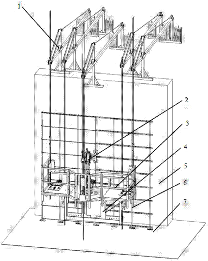
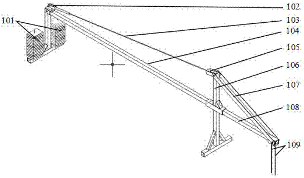
[0041] The present embodiment adopts the above connection method, wherein the length of the front beam 108 in the suspension mechanism 1 is 1460 millimeters; the length of the middle beam 104 is 6000 millimeters, and the height of the column 106 is 1000 mm; the front beam 108, the column 106 and the middle beam 104 are all Made of square steel pipe (100×100), with a thickness of 10mm and a cross-sectional area of ​​0.36e -2 m 2 ; The horizontal angle of the cable-stayed steel wire rope 103 is 28.1°, and the flexural modulus is 0.984e -3 , the moment of inertia is 0.492e -5 I y Swing arm type safety lock 110 is installed on the sling 109, this lock can automatically lock the sling and stop running, and can not reset automatically. The body 301 of the aerial work platform is 3900×1800×1600 mm in length, width and height, and it is built by welding and bolting with the material of round structural steel Q235. The aerial work platform 3 includes a platform body 301, a platform...

Embodiment 2

[0043] The connection and positional relationship of each part in the present embodiment are the same as embodiment 1, the difference is that the horizontal included angle of the cable-stayed wire rope 103 is 45 ° in the present embodiment, the length ratio of the length of the middle beam 104 and the front beam 108 is 3.5; The work platform 3 also includes a platform hoist mounting plate 303, the platform hoist 302 is fixed on the guardrail 3012 through the platform hoist mounting plate 303, the aspect ratio of the bottom plate 3011 is 3:1, and a main beam 30112 is attached to the bottom of the bottom plate 3011 (see Figure 9 ), the main beam 30112 extends from the vicinity of the edge of the bottom plate to the bottom of the manipulator mounting seat 3013, the projection of the main beam on the bottom plate and the projection of the suspension force point of the sling 109 on the guardrail 3012 on the bottom plate to the center of the installation seat ring 30132 The connect...

Embodiment 3

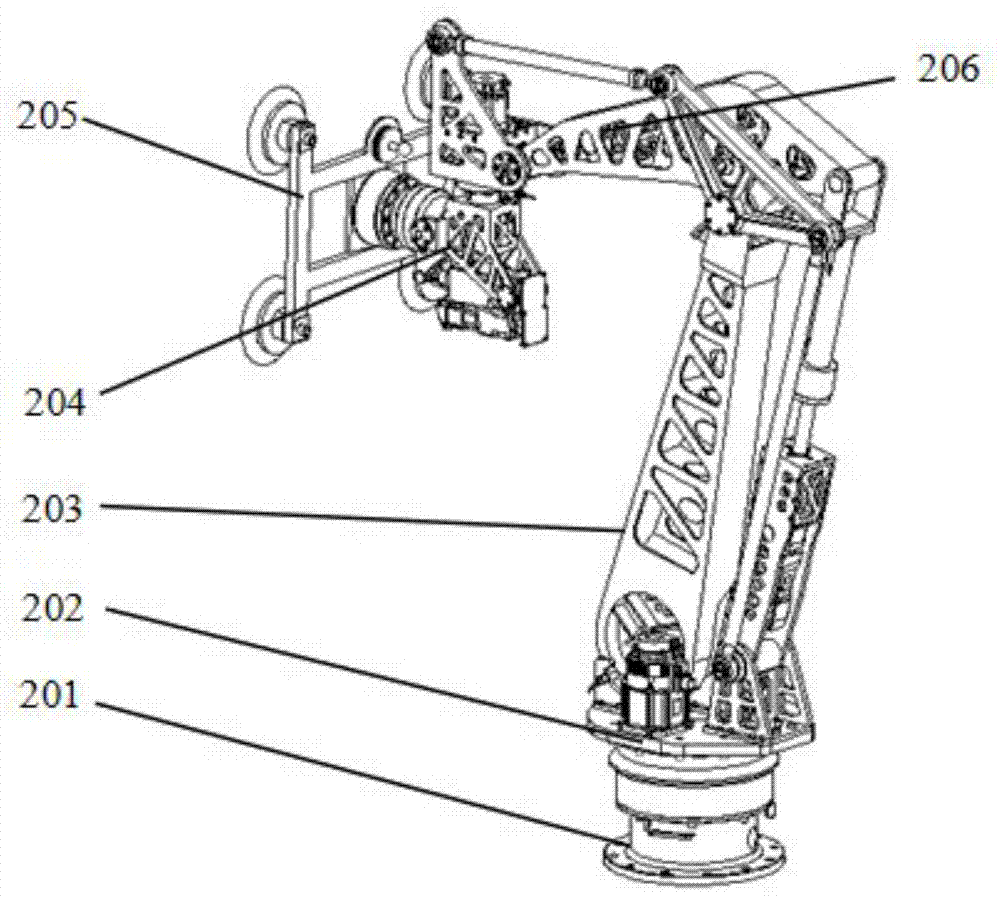
[0045] The present embodiment is the same as the connection and positional relationship among the embodiment 2, the difference is that the horizontal included angle of the cable-stayed wire rope 103 is 25 ° in the present embodiment, the length ratio of the length of the middle beam 104 and the front beam 108 is 4.5; the base plate 3011 The aspect ratio is 1.6:1. Both the robot arm 2033 and the robot forearm 2063 are made of hollowed-out plates, and the hollowed-out shape is triangular. The selection of the hollowed-out shape is based on the requirement of ensuring the strength and rigidity of the manipulator itself, and further reduces the weight of the manipulator itself. The end effector 205 includes a suction cup holder 2051, an actuator suction cup 2053 and a six-dimensional force sensor 2052. The shape of the suction cup holder 2051 is I-shaped, and one actuator suction cup 2053 is connected to each of the four corners of the I-shaped suction cup holder. One side of the ...


PUM


Abstract

The invention relates to a high-altitude board installation mechanical system. The high-altitude board installation mechanical system comprises a suspension mechanism, a manipulator, a high-altitude operation platform and an automatic feeding mechanism, wherein the suspension mechanism is installed on a roof of a building in the working process and bears the suspension work of the high-altitude operation platform; the suspension mechanism is provided with a sling; elevators are arranged on the high-altitude operation platform and the automatic feeding mechanism; the high-altitude operation platform and the automatic feeding mechanism move through mutual cooperation of the corresponding sling and the corresponding elevators; the automatic feeding mechanism is arranged between the high-altitude operation platform and the operation stand surface; the manipulator is installed on the high-altitude operation platform. The high-altitude board installation mechanical system is characterized in that the manipulator has six degrees of freedom and comprises a base, a rotary machine frame, a big arm parallelogram mechanism, a tail end gesture adjusting device, a tail end actuator and a small arm parallelogram mechanism; the base, the rotary machine frame, the big arm parallelogram mechanism, the small arm parallelogram mechanism, the tail end gesture adjusting device and the tail end actuator are sequentially connected.

Description

technical field [0001] The invention relates to the technical field of automatic mechanical system and building installation, in particular to a high-altitude plate installation mechanical system. Background technique [0002] At present, with the rapid development of science and technology, people's demand and requirements for automated mechanical systems are getting higher and higher, and automated mechanical systems have been applied in more and more fields. As a major industry in the national economy, the construction industry has a much lower application level of mechanical systems than other industries. At the same time, compared with other industries, the working environment in the construction industry is often characterized by unstructured and uncertain characteristics. Therefore, construction machinery, as a brand-new application field, requires the mechanical system to have high flexibility and stability, as well as certain characteristics of environmental adapta...

Claims


Application Information

Patent Timeline
Patent Type & Authority Applications(China)
IPC IPC(8): E04G21/16E04G21/18
Inventor 李铁军杨冬刘智光李小琦章鹏赵海文
Owner HEBEI UNIV OF TECH
Learn More