Engine position management system and management method

A management system, engine technology, applied in the direction of engine control, machine/engine, mechanical equipment, etc., can solve problems such as traffic accidents, car breakdowns, damaged engines, etc.

Active Publication Date: 2015-07-01
LIANCHUANG AUTOMOBILE ELECTRONICS
View PDF5 Cites 42 Cited by
  • Summary
  • Abstract
  • Description
  • Claims
  • Application Information

AI Technical Summary

Problems solved by technology

[0003] When the crankshaft or camshaft sensor fails, if the fault cannot be effectively identified or effective measures cannot be taken after identifying the faul

Method used


Image

  • Engine position management system and management method
  • Engine position management system and management method
  • Engine position management system and management method

Examples


Embodiment Construction

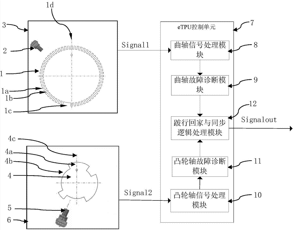
[0063] Such as figure 1 As shown, it is a schematic structural diagram of the engine position management system of the embodiment of the present invention; the engine position management system of the embodiment of the present invention includes:

[0064] The crankshaft signal plate 1 is arranged on the crankshaft of the engine and rotates with the crankshaft. The outer circumference of the crankshaft signal plate 1 is formed with a plurality of first protruding teeth 1a, and between two adjacent first protruding teeth 1a A first tooth gap is formed between them, and the first tooth gap includes a first large tooth gap 1c and a plurality of first small tooth gaps 1b, the center angles of each of the first convex teeth 1a are the same, and each of the first small tooth gaps The central angles of the tooth gaps 1b are the same as the central angles of the first protruding teeth 1a, and the central angles of the first large tooth gaps 1c are 5 times the central angle of one of th...


PUM

PropertyMeasurementUnit
Central angleaaaaaaaaaa

Abstract

The invention discloses an engine position management system. The engine position management system comprises a crankshaft signal panel, a crankshaft position sensor, a camshaft signal panel, a camshaft position sensor and an eTPU control unit, wherein the crankshaft signal panel comprises multiple convex teeth and tooth gaps; the tooth gaps have a large tooth gap for positioning; and the camshaft signal panel comprises three convex teeth with different central angles and tooth gaps. The eTPU control unit comprises a crankshaft signal processing module, a crankshaft fault diagnosis module, a camshaft signal processing module, a camshaft fault diagnosis module and a limp return and synchronous logic processing module. The engine position management system can use crankshaft signals and camshaft signals for realizing quick cylinder judgment and synchronization of an engine when the camshaft position sensor and the camshaft position sensor are normal, and can use another sensor for realizing the cylinder judgment synchronization and providing the angle information with limited precision to realize the limb return of the engine when one sensor is broken down. The invention further provides a management method of the engine position management system.

Description

technical field [0001] The invention relates to an engine, in particular to an engine position management system; the invention also relates to a management method of the engine position management system. Background technique [0002] In order to improve the economy, stability and emission of contemporary engines, it has become an inevitable trend to adopt advanced electronic control units. The focus of engine control is to find the mechanical position of the engine accurately and quickly, and the control accuracy of the electronic control system largely depends on the accuracy and precision of the engine's operating position. At present, the industry mainly collects the crankshaft signal and the camshaft signal at the same time, and combines the two signals as the main means of engine position measurement. The crankshaft signal is read by the crankshaft sensor and the camshaft signal is read by the camshaft sensor. The crankshaft sensor consists of a circular metal turnt...

Claims


Application Information

Patent Timeline
IPC IPC(8): F02D45/00
Inventor 祁儒明刘翔盛旭威
Owner LIANCHUANG AUTOMOBILE ELECTRONICS
Why Eureka
Try Eureka