
Laser collaboration temperature control and seal mounting base

A laser and mounting base technology, applied in the laser field, can solve the problems of the overall structure of the laser cannot be used together, the current drive and temperature drive cable interfaces are separated, the laser beam collimation adjustment is cumbersome and inflexible, etc., so as to reduce the overall structure volume and improve the Stability and reliability, effect of simplified longitudinal control

Active Publication Date: 2015-07-01
NINGBO HAIERXIN OPTOELECTRONICS TECH CO LTD
View PDF5 Cites 5 Cited by
  • Summary
  • Abstract
  • Description
  • Claims
  • Application Information

AI Technical Summary

Problems solved by technology

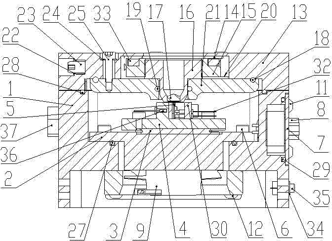
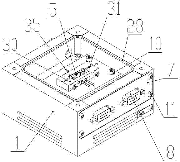
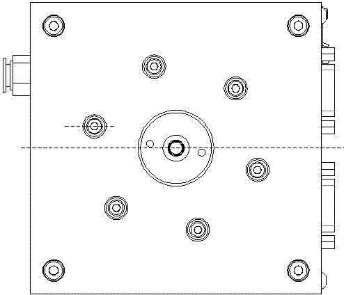
[0013] Aiming at the technical defects existing in the existing products on the market, the invention designs the collimation temperature-controlled sealing mounting seat of the laser to solve the heat dissipation and temperature control of the laser, the current drive and temperature drive of the laser which cannot be solved by the existing products on the market Discrete cable interfaces, non-airtight, cumbersome and inflexible adjustment of laser beam alignment, and the inability of the overall structure of the laser to cooperate with existing standard brackets on the market enable the laser to work stably in an airtight environment. In order to control the temperature and heat dissipation of the laser, the cooling sheet, thermistor and fan are equipped with a three-dimensional precision collimation adjustment mechanism on the light emitting end of the laser, which is easy to operate and reliable, and provides a reliable structural technical guarantee for the use of the laser

Method used


Image

  • Laser collaboration temperature control and seal mounting base
  • Laser collaboration temperature control and seal mounting base
  • Laser collaboration temperature control and seal mounting base

Examples


Embodiment Construction

[0037] The present invention will be further described below in conjunction with the accompanying drawings and embodiments.

[0038] The parts of device of the present invention are as follows:

[0039] The frame body 1 is in the shape of a cuboid and is used to surround other components to form a closed internal environment and play the role of protection, support and installation;

[0040] Sealed DB9 fixing plate 7, located on the side of the frame, used to fix and seal DB9 electronic connector 8;

[0041] Sealed DB9 electronic connector 8, two, respectively used to connect the standard connectors of laser current drive and temperature drive;

[0042] The vibration isolation fan 9 is arranged on the bottom surface of the mounting base, and is used to accelerate the internal air flow of the mounting base to accelerate heat dissipation; the vibration isolation fan is provided with a switch 34, which is located at the bottom right of the sealed DB9 electronic connector, and is u...


PUM


Abstract

The invention belongs to the technical field of laser and particularly relates to a laser collaboration temperature control and seal mounting base. A three-dimensional adjusting system is designed according to a collaboration lens adjusting device of the mounting base; an upper cover plate of a collaboration lens is provided with three dimensions X, Y and Z; the adjustment of the dimensions X and Y are implemented through adjusting screws of two sides of a rotary cover, and the adjustment of the dimension Z is implemented by changing the rotating direction of a collaboration lens mounting base; an inner base unit of the mounting base adopts the tightness design entirely. The adjustment of the dimensions X and Y and that of the dimension Z of a semiconductor laser collaboration system are separated, the adjusting device is simplified, the tightness of the inner base unit is guaranteed, and the whole performances of the laser system are improved.

Description

technical field [0001] The invention belongs to the technical field of lasers, and in particular relates to a collimation installation device of a laser. Background technique [0002] With the development of optoelectronic technology, semiconductor lasers are becoming more and more popular as the core light source in laser sensing, laser communication and other products due to their light weight, high efficiency, low energy consumption, long life and other advantages. Therefore, in recent years, the demand for supporting products based on semiconductor laser light source (hereinafter referred to as "laser") is also increasing day by day. The technical level of the existing laser supporting devices in my country is relatively low, especially those laser supporting products that have high technical requirements for laser source alignment, air tightness, and laser current temperature control drive connection can only be imported from abroad, which is not only expensive but also...

Claims


Application Information

Patent Timeline
Patent Type & Authority Applications(China)
IPC IPC(8): H01S5/022H01S5/024
Inventor 王胤
Owner NINGBO HAIERXIN OPTOELECTRONICS TECH CO LTD
Learn More