
Full-rotor hub motor

A technology of rotor hub and hub, applied in electromechanical devices, electrical components, electric components, etc., can solve the problems of limiting the performance of electric vehicles, large working current, heavy weight, etc., to facilitate large-scale industrial production, high efficiency, wide area, carbon Less brush wear effect

Inactive Publication Date: 2015-07-01
河南超微电动汽车有限公司
View PDF0 Cites 3 Cited by
  • Summary
  • Abstract
  • Description
  • Claims
  • Application Information

AI Technical Summary

Problems solved by technology

The low-speed motor is a kind of external transmission motor, the stator is in the middle, the rotor is on the outside, the rotor and the hub are integrated, the structure is simple, but there is no speed change mechanism, and the low-speed performance is poor. Among them, the brush motor has a low cost, but the weight is large , high working current, poor climbing performance; the low-speed brushless motor itself has a simple structure and few parts, but its controller has a complex structure, high price, and poor reliability
The hub and the motor of the high-speed brushed motor are two parts. The motor is installed in the hub and drives the hub to run through the planetary gear reduction system. Therefore, it has good climbing performance and high technical content, but it is difficult to process and has a short service life. only reach 75%
It can be seen that the performance of the motor limits the improvement of the performance of the electric vehicle, and the structure of the hub motor needs to be improved to improve the performance of the electric vehicle

Method used


Image

  • Full-rotor hub motor
  • Full-rotor hub motor

Examples


Embodiment Construction

[0012] Below in conjunction with accompanying drawing and embodiment do further description:

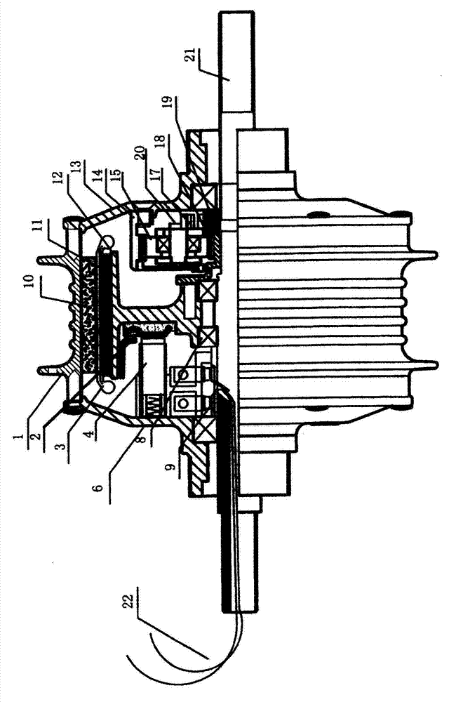
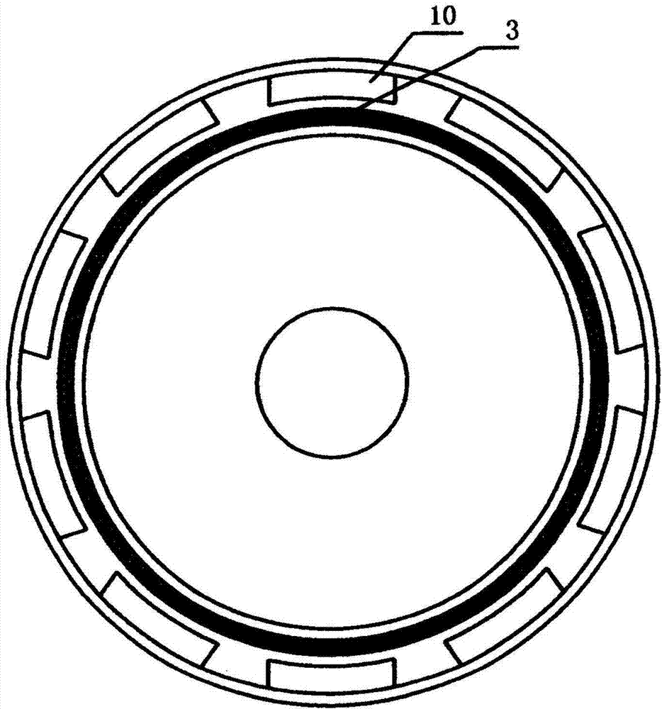
[0013] See attached figure 1 And attached figure 2 As shown, the full-rotor hub motor includes a motor shaft 21, a hub shell, an inner rotor frame 12 and a planetary reduction mechanism. The hub shell includes a motor iron shell 1, a permanent magnet 10 fixed to the inner ring of the motor iron shell 1 and The left end cover 6 and the right end cover 13 fixedly connected with the motor iron shell 1, the left end cover 6 and the right end cover 13 are fixed on the motor shaft 21 through bearings, so that the hub shell constitutes the outer rotor of the motor, and the inner rotor frame 12 A ring-shaped yoke 11 is fixed, and an armature 3 is fixed on the outer surface of the yoke 11. The inner rotor frame 12 is connected with the motor shaft 21 through the inner rotor bearing 8 to form an inner rotor, and one side of the inner rotor frame 12 is fixedly connected. With the commutator ...


PUM


Abstract

A full-rotor hub motor comprises a motor shaft. A wheel hub casing is fixed on the motor shaft via a bearing, and serves as an external rotor of the motor. An internal rotor and a planetary deceleration mechanism are included, a sun gear of the planetary deceleration mechanism is fixedly connected with the internal rotor, an external gear is fixedly connected with the external rotor, a planetary gear carrier is fixedly connected the motor shaft via a clutch, the sun gear and the external gear rotate in opposite directions, and the internal rotor connected to the sun gear and the external rotor connected to the external gear rotate in opposite directions. The motor does not include a stator, when the motor is powered on, the internal rotor rotates in the direction, opposite to the moving direction of a wheel, at a high speed, the external gear is fixed on the hub casing, and thus, the hub casing drives the wheel to move forwards.

Description

technical field [0001] The invention belongs to the field of motors, and relates to a full-rotor hub motor suitable for electric vehicles. Background technique [0002] At present, most of the electric vehicles on the domestic market use wheel hub motors, and the motors drive the hubs, which in turn drive the wheels to rotate. Judging from the structure of existing hub motors, they are mainly divided into high-speed motors and low-speed motors, among which there are brush motors and brushless motors. The low-speed motor is a kind of external transmission motor, the stator is in the middle, the rotor is on the outside, the rotor and the hub are integrated, the structure is simple, but there is no speed change mechanism, and the low-speed performance is poor. Among them, the brush motor has a low cost, but the weight is large , the working current is large, and the climbing performance is poor; the low-speed brushless motor itself has a simple structure and few parts, but its...

Claims


Application Information

Patent Timeline
Patent Type & Authority Applications(China)
IPC IPC(8): H02K16/00H02K7/116B60K7/00
CPCB62M11/16B60K7/0007B60K17/046B60K2007/0038B60K2007/0092B62M6/65H02K16/005H02K7/116
Inventor 张大宝贾学思董勇纪
Owner 河南超微电动汽车有限公司
Learn More