Mixed monitoring system of digital HD video and analog HD video and construction method

A high-definition video and monitoring system technology, applied in closed-circuit television systems, television systems adapted to optical transmission, cable transmission adaptation, etc., can solve problems such as high cost, inability to mix networking, and large amount of upgrades and renovations, reducing construction costs. The effect of minimizing the cost of modification and upgrading, and simplifying the installation and commissioning work

Inactive Publication Date: 2015-07-01
TIANJIN YIHUA MICROELECTRONICS
View PDF0 Cites 5 Cited by
  • Summary
  • Abstract
  • Description
  • Claims
  • Application Information

AI Technical Summary

Problems solved by technology

[0005] The invention provides a hybrid monitoring system and implementation method of digital high-definition video and analog standard-definition video, which overcomes the fact that the high-definition digital video optical fiber monitoring system and the traditional analog video optical fiber monitoring system are independent of each other in the existing monitoring technology and cannot be mixed. The upgrading and reconstruction of the existing analog video fiber optic monitoring system requires a large amount of construction and high cost

Method used


Image

  • Mixed monitoring system of digital HD video and analog HD video and construction method
  • Mixed monitoring system of digital HD video and analog HD video and construction method
  • Mixed monitoring system of digital HD video and analog HD video and construction method

Examples


Embodiment 1

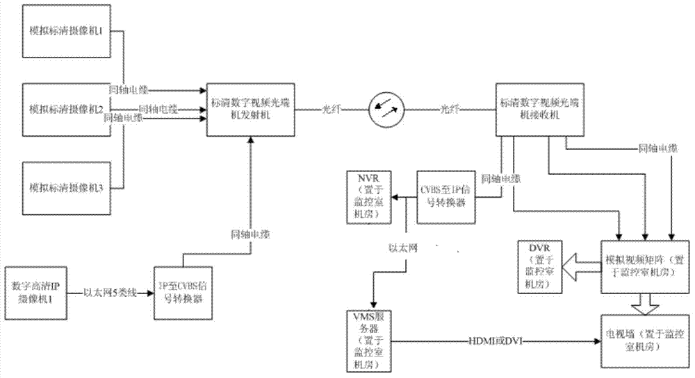
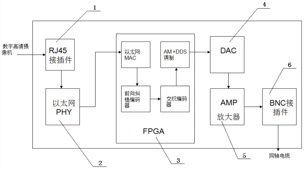
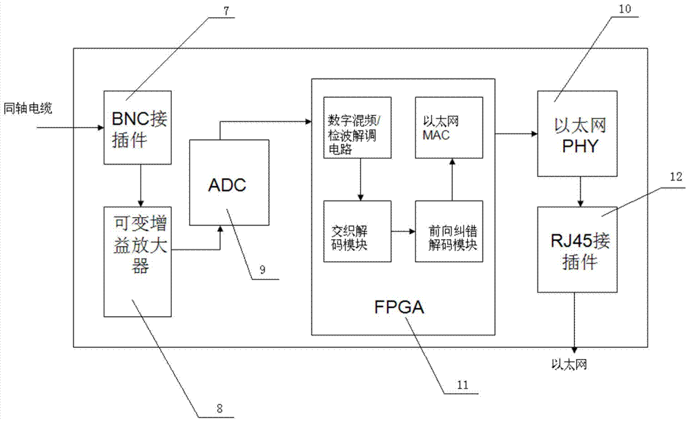
[0034] Example 1: as figure 2 As shown, the digital high-definition IP camera outputs an IP signal. The high-definition camera generally supports a maximum resolution of 1920x1080 / 60 frame format high-definition video, which is compressed and packaged into IP format. The data rate is usually 2Mbps~40Mbps, because the bandwidth is too high and the signal format is different. Matching and cannot directly pass through the digital video optical transceiver behind; it needs to be introduced into the first Ethernet physical interface transceiver 2 through the first RJ45 connector 1 of the IP-to-CVBS-like signal converter, and converted into a digital signal, and then sent to the first RJ45 connector. In an FPGA chip 3; the first Ethernet media access controller in the first FPGA chip 3 recovers the complete IP data packet, repackages the content, and sends it to the forward error correction coding module, and the forward error correction coding The module performs forward error cor...

specific Embodiment

[0035] like Figure 4 As shown, another specific embodiment created by the present invention is: an IP to CVBS-like signal converter is integrated into a digital high-definition IP camera as a functional module, and the new digital high-definition IP camera consists of a casing, a lens 13, an image sensor 14, The image processor 15, the FPGA module 17 and the memory 16 are formed, the image processor 15 is electrically connected to the image sensor 14, the FPGA module 17 and the memory 16, and the lens is electrically connected to the image sensor 14, wherein the image sensor 14 is preferably a CMOS / CCD image sensor, the memory 16 is a DRAM memory;

[0036] The FPGA module 17 includes a network module, an encoder and a modulation module, the encoder is connected to the modulation module, and the modulation module is electrically connected to the third BNC connector 20 through the second D\A converter 18 and the amplifier 19, and the third The BNC connector 20 is a coaxial cab...


PUM


Abstract

The invention creatively provides a mixed monitoring system of a digital HD video and an analog HD video and a construction method. The system is a digital HD video fiber monitoring system or digital HD/ analog SD mixed video fiber monitoring system which is smooth updated from the existing analog SD video fiber monitoring system. With the adoption of the mixed monitoring system, optical fibers are not needed to be arranged again, an optical transmission device is not needed to be replaced; a camera holder is not needed to be replaced, and a camera detector can be simply replaced; the system has the characteristics of minimizing the construction load, and minimizing the reconstruction and updating cost.

Description

technical field [0001] The invention relates to the field of video optical fiber monitoring, in particular to a mixed monitoring system and construction method of digital high-definition video and analog standard-definition video. Background technique [0002] At present, video surveillance is rapidly changing from analog standard definition to digital high definition, the market is huge and the growth rate is amazing. But in all current system solutions, digital high-definition video surveillance and analog standard-definition video surveillance can hardly be integrated. Especially in the field of long-distance optical transmission, because the monitoring system requires real-time and reliability, the traditional analog standard-definition video optical fiber monitoring is mainly completed by digital video optical transceivers. [0003] In the field of digital high-definition video optical fiber monitoring, the current domestic full-IP high-definition video optical fiber m...

Claims


Application Information

Patent Timeline
Patent Type & Authority Applications(China)
IPC IPC(8): H04N7/18H04N7/22
Inventor 杨利民
Owner TIANJIN YIHUA MICROELECTRONICS
Why Eureka
Try Eureka