Check patentability & draft patents in minutes with Patsnap Eureka AI!

circuit interrupting device

A circuit and crowbar circuit technology, applied in the direction of circuits, circuit devices, emergency protection circuit devices, etc., can solve the problems of high steady-state power, loss, etc.

Active Publication Date: 2017-09-08
GENERAL ELECTRIC TECH GMBH
View PDF7 Cites 1 Cited by
  • Summary
  • Abstract
  • Description
  • Claims
  • Application Information

AI Technical Summary

Problems solved by technology

This scheme achieves a response time in the millisecond range, but has the disadvantage of high steady-state power loss

Method used


Image

  • circuit interrupting device
  • circuit interrupting device
  • circuit interrupting device

Examples


Embodiment Construction

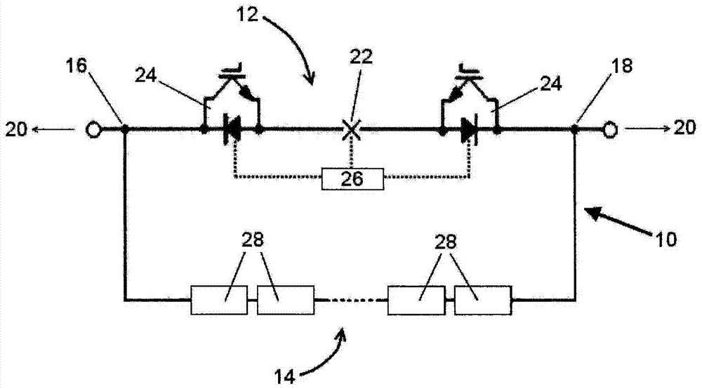
[0094] A first circuit interruption device 10 according to a first embodiment of the present invention is shown in figure 1 .

[0095] The first circuit interruption device 10 includes a main branch 12 , an auxiliary branch 14 and first and second terminals 16 , 18 . Each main branch 12 and auxiliary branch 14 extends between first and second terminals 16 , 18 .

[0096] In use, the first and second terminals 16 , 18 are connected to a DC grid 20 .

[0097] The main branch 12 comprises a switching device in the form of a mechanical switching element 22 , such as a vacuum interrupter switch, which is connected in series with a plurality of semiconductor switching elements in the form of a main IGBT 24 . The first circuit interruption device 10 also includes a main switching control unit 26 for controlling switching of the mechanical switching element 22 and the plurality of main IGBTs 24 .

[0098] In other embodiments, it is contemplated that the number of mechanical switch...


PUM


Abstract

A switching device (28) comprising a primary switching block (30) comprising at least one semiconductor switch (34) and a switching control unit (32) to control switching of the or each semiconductor switch (34). The switchgear also includes a crowbar circuit (46) including a crowbar switch (56) switchable to selectively allow current to flow through the crowbar switch (56) to bypassing the or each switch module; and a secondary switch block including a switch element (58) connected across the control electrode and cathode of the crowbar switch (56). The switching element (58) is in communication with the switching control unit (32) to receive, in use, a signal generated by the switching control unit (32) when the primary switching block (30) is operating within predetermined operating parameters. Control signal (66).

Description

technical field [0001] The invention relates to a switchgear for use in high voltage direct current (HVDC) power transmission, a circuit interruption device comprising at least one such switchgear, and a crowbar circuit. Background technique [0002] In a power transmission network, alternating current (AC) power is typically converted to direct current (DC) power for transmission via overhead lines and / or submarine cables. This conversion does not need to compensate for the effect of AC capacitive loading imposed by the transmission line or cable, thereby reducing the cost per kilometer of the line and / or cable. Conversion from AC to DC thus becomes cost-effective when power needs to be transmitted over long distances. [0003] Power conversion from AC to DC is also used in transmission networks where it is necessary to interconnect AC networks operating at different frequencies. In any such transmission network, converters are required at each intersection of AC and DC p...

Claims


Application Information

Patent Timeline
Patent Type & Authority Patents(China)
IPC IPC(8): H02H3/087H02H9/04H01H33/59H03K17/0814
CPCH02H3/087H02H9/043H03K17/08148H03K17/0828H03K17/127H03K17/305H03K17/73H02H9/02H02H9/04
Inventor C·C·戴维森
Owner GENERAL ELECTRIC TECH GMBH
Features
  • R&D
  • Intellectual Property
  • Life Sciences
  • Materials
  • Tech Scout
  • Unparalleled Data Quality
  • Higher Quality Content
  • 60% Fewer Hallucinations
Learn More