Power source device

A technology of power supply device and power supply, which is applied in the direction of electric device, circuit device, DC network circuit device, etc. It can solve the problems of increased conduction loss, increased number of components, and large-scale reactors, etc., and achieves the goal of reducing voltage fluctuations. Effect

Active Publication Date: 2015-07-01
HONDA MOTOR CO LTD
View PDF4 Cites 7 Cited by
  • Summary
  • Abstract
  • Description
  • Claims
  • Application Information

AI Technical Summary

Problems solved by technology

[0011] In addition, since the power supply device of Patent Document 1 includes four first to fourth relays and a boost converter, the number of parts required for the device configuration increases.
Therefore, there arises a problem that the size of the device is increased and the cost required to configure the device is high.
[0012] In addition, in the power supply system of Patent Document 2, for example, when switching from the parallel connection state to the series connection state, since the voltage of each DC power supply is boosted to the series voltage of the series connection state (for example, approximately 2 times, etc.), the maximum magnetic flux change increases, and in addition to the need to increase the size of the reactor, there is also an increase in conduction loss due to the inclusion of two switching elements in each current path in the series connection state and the parallel connection state. The problem
[0013] In addition, in the power supply system of Patent Document 2, since the total interlinkage flux of the reactor tends to increase as the boost rate increases, the loss increases and the reactor needs to be enlarged.

Method used


Image

  • Power source device
  • Power source device
  • Power source device

Examples


Embodiment Construction

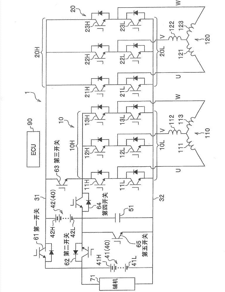
[0041] refer to Figure 1 to Figure 12 , an embodiment of the present invention will be described.

[0042] The power supply device 1 of the present embodiment is a device mounted on a series-type hybrid vehicle (electric vehicle) not shown in the figure, and transmits and receives electric power between the first motor generator 110 and the second motor generator 120 . The first motor generator 110 is connected to an internal combustion engine (power source) not shown, and transmits and receives power to and from the internal combustion engine. The second motor generator 120 is connected to driving wheels (not shown), and transmits power to and from the driving wheels.

[0043]

[0044] The first motor generator 110 has the function of a motor (electric motor) and the function of a generator (generator). That is, since the first motor generator 110 is arranged on the side of the internal combustion engine, it mainly functions as a generator by power from the internal comb...


PUM


Abstract

The purpose of the present invention is to provide a power source device of simple configuration, capable of reducing the voltage fluctuation when switching a power source mode between a parallel power mode and a serial power mode. The power source device comprises: a power source main body (40) having a first secondary battery (41) and a second secondary battery (42); a power-mode switching means for switching the power source device between a parallel power mode, a serial power mode, and a second power source solo mode; a first inverter (10); and an inverter connection mode switching means for switching the power source device between a first connection mode in which the power source main body (40) is connected to the first inverter (10), and a second connection mode in which the first inverter (10) is connected in series to the power source main body (40) while the power source main body (40) is in the second power source solo mode. In the case of switching the power mode from the parallel power mode to the serial power mode, the connection mode is switched to the first connection mode and the first motor generator (110) is actuated as a motor, after which the power mode is switched to the second power source solo mode and the connection mode is switched to the second connection mode so that the power-mode switching means switches the power source mode to the serial power mode after the second secondary battery (42) and the first inverter (10) as the power source have been connected in series.

Description

technical field [0001] The invention relates to a power supply device. Background technique [0002] Conventionally, for example, there is known a power supply device that includes four first to fourth relays, two secondary batteries, and a boost converter. The secondary battery is switched between a series connection state and a parallel connection state, and is connected to an electric load (see Patent Document 1). [0003] In addition, conventionally, for example, there is known a power supply system that includes four first to fourth switching elements, two reactors, and two DC power supplies, adjusts the voltage applied to an electric load, and simultaneously switches the two DC power supplies. It is connected to an electric load in a series connection state and a parallel connection state (refer to Patent Document 2). [0004] prior art literature [0005] patent documents [0006] Patent Document 1: Japanese Patent Laid-Open No. 2012-60838 [0007] Patent Documen...

Claims


Application Information

Patent Timeline
Patent Type & Authority Applications(China)
IPC IPC(8): H02P27/06B60L11/18B60L3/00H02J1/00H02J1/10
CPCB60L2240/423B60L2240/526H02J7/0024H02P27/06B60L2210/30B60L11/1803H02P5/74Y02T10/648B60L2210/42B60L7/14B60L2240/527B60L2240/529B60L2240/547Y02T10/7241Y02T10/7055B60L2220/42Y02T10/7005B60L50/51B60L58/19H02J2310/48Y02T10/64Y02T10/70Y02T10/72H02P23/00
Inventor 高桥忠伸
Owner HONDA MOTOR CO LTD
Why Eureka
Try Eureka