Fish-tail imitating propeller

A thruster and fishtail technology, which is applied in the field of bionic fishtail thrusters, can solve the problems of large noise pollution, high quality, high energy consumption, etc., and achieve the effects of improving transmission efficiency, simple structure and shortening the transmission chain

Active Publication Date: 2015-07-08
HARBIN ENG UNIV
View PDF6 Cites 2 Cited by
  • Summary
  • Abstract
  • Description
  • Claims
  • Application Information

AI Technical Summary

Problems solved by technology

At present, the research on the propulsion technology of underwater vehicles mainly includes three categories: traditional propeller propulsion, jet propulsion, and bionic caudal fin propulsion. Considering that the traditional propeller propulsion method has the disadvantages of large noise and high energy consumption, It cannot meet the needs of some special fields and has certain limitations; the way of jet propulsion is non-polluting. However, the propulsion efficiency is low, and the large-flow jet is easily scanned by radar and other equipment, so it can only be applied to small-scale equipment manufacturing , therefore, the research on bionic caudal fin technology highlights the important research significance
[0003] In the current research on bionic caudal fin propulsion technology, bionic fish robots with multiple degrees of freedom are mainly manufactured through complex mechanical structures. This design has a series of defects such as large mass, inflexible underwater movement, and low underwater propulsion efficiency. The important thing is that in the process of underwater operation, it has greater underwater disturbance
In addition, since most robots are driven by hydraulic pressure, pneumatic power or electric motors with deceleration mechanisms, there are problems such as large noise pollution.

Method used


Image

  • Fish-tail imitating propeller
  • Fish-tail imitating propeller
  • Fish-tail imitating propeller

Examples


Embodiment Construction

[0018] The present invention is described in more detail below in conjunction with accompanying drawing example:

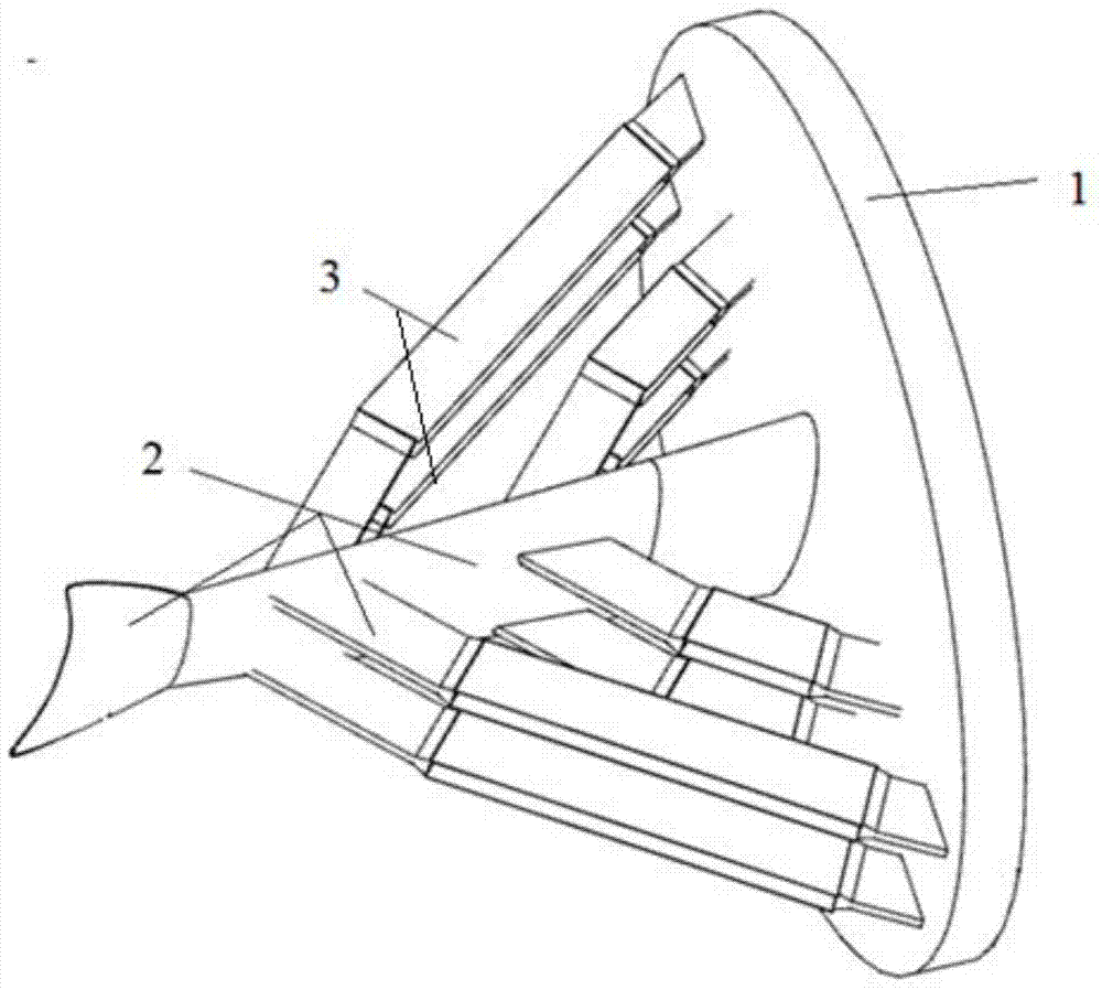
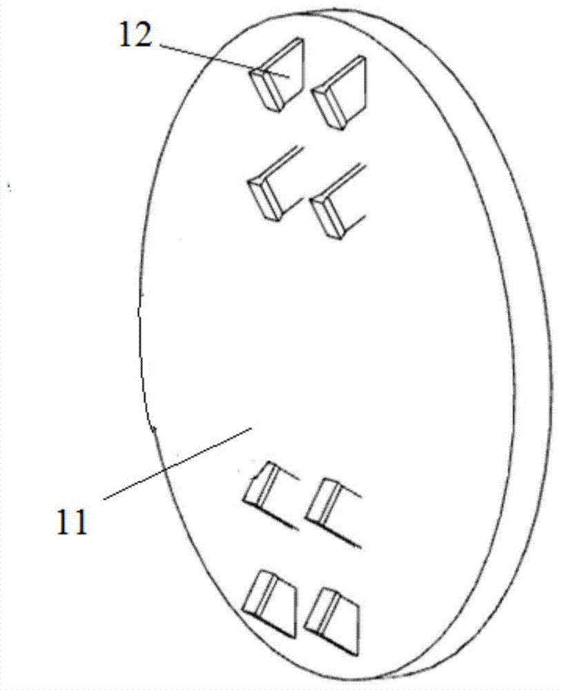
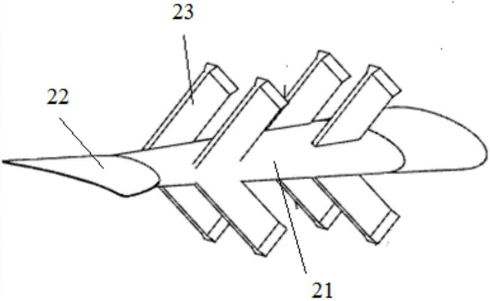
[0019] combine figure 1 , the bionic fishtail thruster includes a base part 1, a swing propulsion part 2 and an imitation muscle driving part 3; as Figure 2-5 As shown, the base part 1 has a support plate 11 with flexible tendons 12 on the support plate; the front end of the swing propulsion part 2 has a flexible trunk 21, the tail end has a flexible caudal fin 22, and the two sides of the flexible trunk have flexible tendons 23, which are symmetrical Distribution; the imitation muscle driving part 3 includes a stretching muscle unit 31; the flexible trunk 21 of the swing propulsion part 2 is connected to the support plate 11 of the base part 1, and the flexible tendons 12 of the base part 1 and the swing propulsion part 2 The flexible ribs 23 of the flexible torso 21 are assembled and connected with the stretching muscle unit 31, forming the structure of the bi...


PUM


Abstract

The invention provides a fish-tail imitating propeller which comprises a base part, swing propelling parts and muscle imitating driving parts. The base part is provided with a supporting plate which is provided with first flexible bars. Flexible bodies are arranged at the front ends of the swing propelling parts, and flexible tail fins are arranged at the tail ends of the swing propelling parts. Second flexible bars are arranged on the two sides of each flexible body, and the second flexible bars are symmetrically distributed. The muscle imitating driving parts comprise muscle stretching units. The front ends of the flexible bodies are matched to be connected to the supporting plate, and the muscle stretching units are connected between the first flexible bars and the second flexible bars. The fish-tail imitating propeller has the advantages of being simple in structure composition and flexible to drive. The swing propelling parts and the muscle imitating driving parts are directly assembled to constitute a driving and transmission system through the flexible bars, and the integration of driving and transmission is achieved. Meanwhile, a transmission chain is shortened, and the transmission efficiency is improved. No noise exists in the driving process, underwater propelling is conducted in a swing mode, and the disturbance to a surrounding water area is lowered.

Description

technical field [0001] The invention relates to an underwater propulsion device, in particular to a bionic fishtail propeller. Background technique [0002] With the increasing development of marine resources, research on underwater vehicles has emerged. As the core part of underwater vehicles, underwater propulsion technology has gained widespread attention in the academic community. At present, the research on the propulsion technology of underwater vehicles mainly includes three categories: traditional propeller propulsion, jet propulsion, and bionic caudal fin propulsion. Considering that the traditional propeller propulsion method has the disadvantages of large noise and high energy consumption, It cannot meet the needs of some special fields and has certain limitations; the way of jet propulsion is non-polluting. However, the propulsion efficiency is low, and the large-flow jet is easily scanned by radar and other equipment, so it can only be applied to small-scale equ...

Claims


Application Information

Patent Timeline
Patent Type & Authority Applications(China)
IPC IPC(8): B63H1/36
Inventor 赵刚孙壮志王好军杨俊杰王志杰王禹健汪川
Owner HARBIN ENG UNIV
Why Eureka
Try Eureka