Steel pipe concrete pile

A technology of steel pipe concrete and concrete, which is applied in the field of building materials, can solve the problems of high production cost and complex structure of pipe piles, and achieve the effect of fast pile formation, strong hammer resistance, and improved bonding

Inactive Publication Date: 2015-07-08
建华建材(蚌埠)有限公司
View PDF8 Cites 12 Cited by
  • Summary
  • Abstract
  • Description
  • Claims
  • Application Information

AI Technical Summary

Problems solved by technology

However, the structure of this pipe pile is relatively complicated and the production cost is high.

Method used


Image

  • Steel pipe concrete pile
  • Steel pipe concrete pile
  • Steel pipe concrete pile

Examples


Embodiment 1

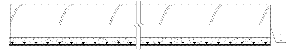
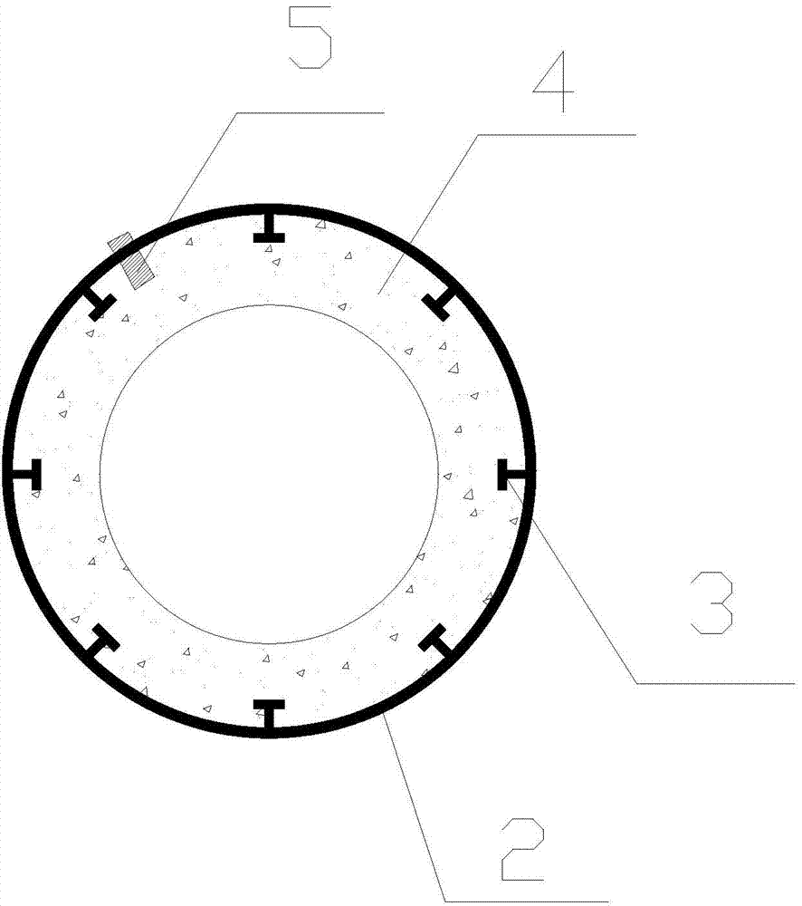
[0029] Such as figure 1 , figure 2 As shown, a concrete-filled steel pipe pile includes an outer steel pipe 2, a spiral rib 5 is fixed on the inner and outer walls of the outer steel pipe 2, and multiple rings of anchors 3 are fixed along the circumference of the inner wall of the outer steel pipe 2. The inner steel pipe 2 is lined with concrete 4, and the end of the outer steel pipe 2 is provided with an end plate 1; the design of the structure of the present invention makes the bite force between the outer steel pipe 2 and the concrete 4 include three parts: the spiral rib 5 and the concrete 4 Engagement force, the anchoring force between the anchor 3 and the concrete 4, the bonding force between the inner wall of the outer steel pipe 2 and the concrete 4, the increased spiral rib 5 and the anchor 3 can greatly improve the bonding between the concrete 4 and the steel pipe, and the combination It is strong, and the anti-strike ability is enhanced, and the concrete and the s...

Embodiment 2

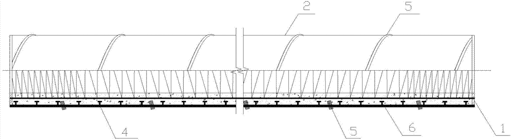
[0038] Such as image 3 , Figure 4 As shown, a concrete-filled steel pipe pile includes an outer steel pipe 2, a spiral rib 5 is fixed on the inner wall of the outer steel pipe 2, and multiple rings of anchors 3 are fixed along the circumference of the inner wall of the outer steel pipe 2. The steel pipe steel pipe 2 is lined with concrete 4, and the end of the outer steel pipe 2 is provided with an end plate 1; the design of the structure of the present invention makes the bite force between the outer steel pipe 2 and the concrete 4 include three parts: the engagement of the spiral rib 5 and the concrete 4 force, the anchoring force between the anchor 3 and the concrete 4, the bonding force between the inner wall of the outer steel pipe 2 and the concrete 4, the increased spiral rib 5 and the anchor 3 can greatly improve the bonding between the concrete 4 and the outer steel pipe 2 , the combination is firm, the anti-strike ability is enhanced, and the concrete and the stee...

Embodiment 3

[0040] Such as Figure 5 As shown, a concrete-filled steel pipe pile includes an outer steel pipe 2, a spiral rib 5 is fixed on the inner wall of the outer steel pipe 2, and multiple rings of anchors 3 are fixed along the circumference of the inner wall of the outer steel pipe 2. The steel pipe steel pipe 2 is lined with concrete 4, and the end of the outer steel pipe 2 is provided with an end plate 1; the design of the structure of the present invention makes the bite force between the steel pipe and the concrete include three parts: the meshing force between the spiral rib 5 and the concrete 4, the anchor The anchoring force between 3 and concrete 4, the bonding force between the inner wall of steel pipe and concrete 4, the added spiral rib 5 and anchor 3 can greatly improve the bonding between concrete 4 and steel pipe, the combination is firm, the anti-strike ability is enhanced, and the blow The concrete 4 and the steel pipe will not be separated during the process. The ...


PUM

PropertyMeasurementUnit
thicknessaaaaaaaaaa

Abstract

The invention provides a steel pipe concrete pile. The steel pipe concrete pile comprises an outer-layer steel pipe; a spiral rib is fixed on the inner wall of the outer-layer steel pipe; a plurality of circles of rivets are fixed at the circumference of the inner wall of the outer-layer steel pipe; the outer-layer steel pipe is lined with a concrete inner layer, and an end plate is arranged at the end portion of the outer-layer steel pipe; according to the structural design, the biting force of the steel pipe and the concrete comprises three parts, namely the biting force of the spiral rib and the concrete, the anchoring force of the rivet and the concrete and the binding force of the inner wall of the steel pipe and the concrete; the added spiral rib rivet is capable of improving the binding of the concrete and the steel pipe to a large extent, so that the concrete and the steel pipe can be bound firmly and the impact resistance can be enhanced, and in the striking process, the concrete and the steel pipe are not separated from each other. According to experimental verification, after the spiral rib is added and the rivet is arranged, the bending resistance and the shear-bearing capacity of the novel pipe pile are improved by 50%.

Description

technical field [0001] The invention relates to the technical field of building materials, in particular to a steel pipe concrete pipe pile for a pile foundation in the civil construction industry. Background technique [0002] In my country's current industrial and civil construction engineering pile foundations, a large number of pile foundations using cast-in-situ piles or steel pipe piles are used. However, its scope of application is limited due to long construction period, difficult quality control and high investment cost. It is used in the engineering fields of retaining walls, bridge piers and abutments, viaduct bents, wharf engineering and offshore engineering, etc., which bear horizontal loads, as well as resisting pile-based buildings subjected to wind loads and earthquakes, which cause horizontal loads with high seismic intensity, such as super high-rise buildings. In the field of construction engineering, steel pipe piles are chosen due to the difficulty of co...

Claims


Application Information

Patent Timeline
Patent Type & Authority Applications(China)
IPC IPC(8): E02D5/30B28B7/30B28B19/00
Inventor 毛永平雷秀清姜卫栋周安季学阳
Owner 建华建材(蚌埠)有限公司
Why Eureka
Try Eureka