
Wing-shaped part

An airfoil and airfoil technology, applied in the field of airfoils, can solve problems such as the need to improve mechanical integrity, and achieve the effect of improving the efficiency of the whole machine

Active Publication Date: 2015-07-08
溧阳市超强链条制造有限公司
View PDF9 Cites 10 Cited by
  • Summary
  • Abstract
  • Description
  • Claims
  • Application Information

AI Technical Summary

Problems solved by technology

[0003] There are various improved airfoils, see for example US6190128B1 which discloses a cooled moving blade for a gas turbine having a contoured base portion formed by an elliptical curved surface, and a straight Surface sections, where rectilinear surface sections are provided at the hub section of the blade where thermal stress is high, provide stress relief, but mechanical integrity needs to be improved

Method used


Image

  • Wing-shaped part
  • Wing-shaped part

Examples


Embodiment Construction

[0016] The composition structure and working principle of the present invention will be described in detail below in conjunction with the accompanying drawings.

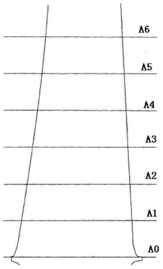
[0017] figure 1 Arbitrary graduations of the airfoil continuing from the reference point A0 at the bottom end to the point A6 at the distal end are enumerated, and the section of each graduation of the airfoil is an airfoil.

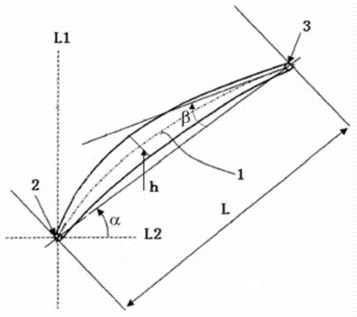
[0018] figure 2 The terms chord length L, installation angle, bend angle β, leading edge radius r, and thickness h used to define the airfoil are exemplified.

[0019] Such as figure 2 As shown, the middle arc 1 is the line connecting the center of the inscribed circle around the airfoil called the middle arc. Leading edge 2 refers to the frontmost point of the arc in the airfoil called the leading edge of the airfoil. Trailing edge 3 refers to the last point of the arc in the airfoil called the trailing edge. The connection between the front and rear edges of the airfoil is called the a...


PUM

PropertyMeasurementUnit
Thicknessaaaaaaaaaa

Abstract

The invention relates to a wing-shaped part. A specific relation between the chord length, the mounting angle and the angle of bend is set, and the equilibrium relation of various indices such as overall efficiency, economic efficiency, mechanical integrity and working service life can be effectively improved.

Description

technical field [0001] The invention relates to an airfoil, in particular to an airfoil for a turbine rotor, a compressor blade or a pump impeller. Background technique [0002] For the design of airfoils used as turbine rotors, compressor blades or pump impellers, there are various design requirements so that the turbine rotors, compressor blades or pump impellers can meet the indicators of overall machine efficiency, economic efficiency, mechanical integrity, etc. included design goals. During the working process of turbine rotors, compressor blades or pump impellers, centrifugal force, gas pressure or vibration will generate stress. The existence of stress will affect the working life of turbine rotors, compressor blades or pump impellers, and even cause shutdown in severe cases. Therefore, it is very critical for the design of the airfoil. [0003] There are various improved airfoils, see for example US6190128B1 which discloses a cooled moving blade for a gas turbine h...

Claims


Application Information

Patent Timeline
IPC IPC(8): F01D5/02F04D29/30F04D29/38F04D29/18
Inventor 蒋俊美蒋俊波蒋阿生
Owner 溧阳市超强链条制造有限公司
Features
  • Generate Ideas
  • Intellectual Property
  • Life Sciences
  • Materials
  • Tech Scout
  • Unparalleled Data Quality
  • Higher Quality Content
  • 60% Fewer Hallucinations
Learn More