Safety shut-off valve

A technology of safety cut-off valve and cut-off mechanism, which is applied in the direction of safety valve, lifting valve, valve details, etc., can solve the problems of reducing the service life of the valve disc, making it difficult to manufacture, and occupying a large space, so as to improve the internal organizational structure and avoid maintenance The effect of assembly error and convenient maintenance and replacement

Inactive Publication Date: 2015-07-08
北京润凡电子制造有限公司
View PDF10 Cites 6 Cited by
  • Summary
  • Abstract
  • Description
  • Claims
  • Application Information

AI Technical Summary

Problems solved by technology

The closing element of this patent adopts the sealing method between the valve disc and the valve port, and the sealing part of the valve port has a raised design, which reduces the service life of the valve disc; the closing components of these two cut-off valves require springs to provide a large force , to help the closing element to achieve sealing, which increases the force of the shut-off valve during manual reset operation; at the same time, when the shut-off valve is open, the O-ring at the valve plate has no protection measures and will be washed by the inflowing gas, so that it cannot Play a good sealing effect, causing loss and safety problems
[0005] The safety cut-off valves in the prior art all use sleeve-guided positioning valve discs, which have high requirements for concentricity and occupy a large space ( figure 1 Cutting cavity 004 and figure 2 Shut-off valve body II), complex structure, difficult manufacture, high cost, and many disassembled parts during maintenance; at the same time, due to the casting shell, the structure is complex, difficult to manufacture, many material defects, and low safety

Method used


Image

  • Safety shut-off valve
  • Safety shut-off valve
  • Safety shut-off valve

Examples


Embodiment Construction

[0033] The present invention will be described in further detail below in conjunction with the accompanying drawings and embodiments.

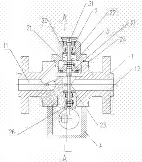
[0034] Such as image 3 with Figure 4 As shown, the safety cut-off valve of the present invention includes a valve body 1, an upper valve body 3 and a cut-off mechanism, the upper valve body 3 is connected to the upper end of the valve body 1 by screws for sealing the valve body 1, and the upper valve body 31 acts as a sealing bearing Pressure, reduce air scour, prolong the life of the valve plate components. The cut-off mechanism includes a cut-off part 2 and a cam connection device 4, and the cut-off part 2 and the cam connection device 4 are separately provided. The cut-off mechanism is arranged in the middle of the valve body 1 for connecting or cutting off the air inlet and the air outlet. The safety cut-off valve of the present utility model also includes a balance valve 6, which is used to connect the air inlet and the air outlet of ...


PUM


Abstract

The invention discloses a safety shut-off valve. The safety shut-off valve comprises a valve body, an upper valve body and a shut-off mechanism. The valve body is provided with a first channel and a second channel, the upper valve body is connected with the upper end of the valve body through a screw and used for sealing the valve body, and the shut-off mechanism is arranged in the middle of the valve body and used for connecting or disconnecting the first channel and the second channel. The safety shut-off valve is characterized in that the shut-off mechanism comprises a shut-off part and a cam connecting device which are separated from each other; the valve body is integrally formed by forged steel in a turn milling mode. The independent cam connecting device is adopted, so that separated repair is facilitated, and the situation that the shut-off valve cannot work normally due to maintenance assembly errors is avoided; the internal structure of the valve body is simple, the forged steel integration valve body is adopted, the internal organizational structure of the valve body is improved, grains are refined, the mechanical properties, such as shock resistance, plasticity and toughness, of the forged steel integration valve body are superior to those of a cast steel valve body, and the safety performance of the valve is improved.

Description

technical field [0001] The invention relates to a safety cut-off valve, in particular to a safety cut-off valve for a gas transmission system. Background technique [0002] Safety cut-off valves are used in gas transmission and distribution systems for emergency cut-off protection. When the pipeline pressure controlled by the shut-off valve is higher or lower than the cut-off set pressure, the safety shut-off valve can cut off the pipeline air flow urgently to protect the downstream equipment. [0003] The Chinese patent application number 200920170968.3 discloses a safety shut-off valve such as figure 1 As shown, it mainly consists of housing 001, air inlet 002, air outlet 003, cut-off chamber 004, release mechanism 005, cut-off valve 006, cut-off spring 007, cut-off valve stem 008, piston 009, pressure regulating spring 0010, connecting rod 0011 , Feedback signal tube 0012 and so on. When this type of cut-off valve is in the open state and reset operation, the trip mech...

Claims


Application Information

Patent Timeline
Patent Type & Authority Applications(China)
IPC IPC(8): F16K17/04F16K1/36F16K1/46F16K31/524F16K31/14
CPCF16K31/52408F16K1/36F16K1/46F16K17/0413F16K17/0486F16K27/02
Inventor 李亚峰吴礼明
Owner 北京润凡电子制造有限公司
Why Eureka
Try Eureka