A tunnel kiln for producing refractory materials

A refractory material and tunnel kiln technology, applied in the field of tunnel kiln, can solve the problems such as the inability to obtain strong support for the thermal insulation layer on the top of the kiln, the inability to set a high height of the sand sealing groove, affecting the production cost and product quality, etc. Eliminate manual labor input, ensure production cost and product quality, and achieve good partition effect

Inactive Publication Date: 2017-03-29
长兴震铭耐火材料有限公司
View PDF6 Cites 0 Cited by
  • Summary
  • Abstract
  • Description
  • Claims
  • Application Information

AI Technical Summary

Problems solved by technology

[0003] 1) The structure setting of the sand seal groove is unreasonable. Due to the limitation of strength, the sand seal groove cannot be set at a high height, resulting in poor partition effect between the steel skirt plates on both sides of the kiln car and the sand seal groove of the side wall, making the cold air It is easy to leak into the kiln, and the hot gas is easy to leak out of the kiln, which affects the production cost and product quality;
[0004] 2) The heat insulation structure of the kiln roof is unreasonably set up, which leads to the inability of strong support for the heat insulation layer of the kiln roof, which limits the thickness of the heat insulation layer of the kiln roof and affects the heat preservation effect;
[0005] 3) The sand in the sand seal tank is continuously lost during the production process, it is inconvenient to manually enter the kiln to add sand, and the efficiency of sand addition is low;
[0006] 4) Insufficient air supply in the inlet section leads to the inability to achieve a good air convection effect in the tunnel kiln, which affects the preheating effect in the preheating section
[0007] 5) The design of the smoke exhaust structure of the existing tunnel kiln is unreasonable, resulting in the inability to achieve a more reasonable temperature adjustment and pressure adjustment effect, which affects the quality of the finished product in the kiln

Method used


Image

  • A tunnel kiln for producing refractory materials
  • A tunnel kiln for producing refractory materials
  • A tunnel kiln for producing refractory materials

Examples


Embodiment Construction

[0035]The present invention will be further described in detail below in conjunction with the accompanying drawings and examples. The following examples are explanations of the present invention and the present invention is not limited to the following examples.

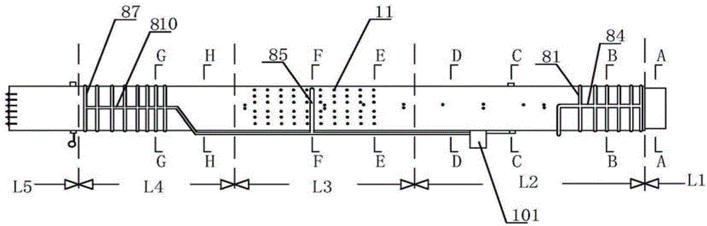
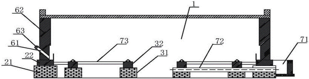
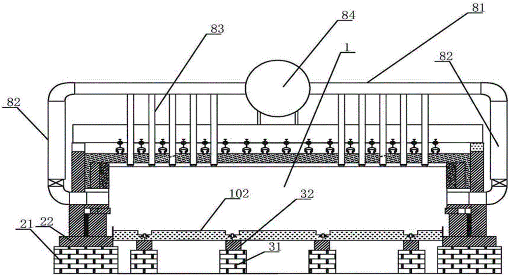
[0036] see Figure 1-Figure 16 The tunnel kiln of this embodiment includes a kiln body extending laterally and a kiln car running in the kiln body. The kiln body includes a kiln roof, a kiln wall and a working channel 1, and the working channel 1 includes an inlet section L1 in the direction of extension. , preheating section L2, roasting section L3, heat preservation section L4 and cooling section L5, the kiln wall includes a wall platform 21 fixed on the foundation, the wall platform 21 is made of rubble bricks, and the wall platform 21 is provided with a cushion layer 22 formed by pouring concrete.

[0037] The first wall layer 23, the second wall layer 24, and the wall heat insulation layer 22 arranged sequentia...


PUM


Abstract

The invention discloses a tunnel kiln used for producing fireproof materials. The tunnel kiln is characterized by comprising a kiln body and a kiln car, wherein the kiln body extends in the transverse direction, and the kiln car is driven inside the kiln body. The kiln body comprises a kiln top, a kiln wall and a working channel, the working channel sequentially comprises an inlet section, a preheating section, a roasting section, a thermal insulation section and a cooling section in the extending direction, and sand seal groove structures are formed in the sides, close to the working channel, of built-up layers of the inlet section, the preheating section, the roasting section, the thermal insulation section and the cooling section and used for sealing the bottom space of the kiln car. The sand seal groove structures are reasonable in arrangement and high in strength, the effect of isolation between steel apron boards on the two sides of the kiln car and the sand seal grooves in the side walls is good, and the overall sealing effect is improved. A thermal insulation structure on the kiln top is arranged reasonably, and in this way, a thermal insulation layer on the kiln top can be supported powerfully and can be arranged to be a thick thermal insulation layer on the kiln top. A sand throwing tube is arranged for throwing sand, sandy soil inside the sand seal grooves can be supplemented at any time in the production process and can be driven forwards by a sand seal cutter, a worker does not need to enter the kiln to add the sand, in this way, labor investment is omitted, the structure is simple, and construction is convenient.

Description

technical field [0001] The invention relates to a tunnel kiln for producing refractory materials. Background technique [0002] Tunnel kiln is generally a long linear tunnel with fixed walls and vaults on both sides and top, and kiln cars run on tracks laid at the bottom. The combustion equipment is installed on both sides of the middle part of the tunnel kiln, which constitutes a fixed high-temperature zone - the firing zone. The high-temperature flue gas generated by combustion flows along the tunnel to the kiln head under the action of the chimney at the front end of the tunnel kiln or the induced draft fan. At the same time, the products entering the kiln are gradually preheated, and this section constitutes the preheating zone of the tunnel kiln. The cold air blows into the kiln tail of the tunnel kiln to cool the products in the last section of the tunnel kiln. After the cold air blows in flows through the products and is heated, it is drawn out and sent to the dryer ...

Claims


Application Information

Patent Timeline
Patent Type & Authority Patents(China)
IPC IPC(8): F27B9/26F27B9/34F27B9/38F27B9/30F27B9/40
Inventor 吴建昌
Owner 长兴震铭耐火材料有限公司
Why Eureka
Try Eureka