Liquefied nitrogen tank

A liquid nitrogen tank and tank body technology, which is applied in the field of liquid nitrogen tanks, can solve the problems of the overall weight of the lifting cylinder, fast consumption of liquid nitrogen, and increased consumption of liquid nitrogen, and achieve the effects of avoiding direct contact, simple design, and excellent performance

Inactive Publication Date: 2015-07-08
GUANGDONG UNIV OF TECH
View PDF5 Cites 9 Cited by
  • Summary
  • Abstract
  • Description
  • Claims
  • Application Information

AI Technical Summary

Problems solved by technology

[0002] The disadvantage of the existing liquid nitrogen tank is that the lifting cylinder is heavy and bulky as a whole, which makes extraction difficult, and it takes a long time to extract the frozen samples in the lifting cylinder
Therefore, it cannot be convenient and fast
[0003] In addition, in order to extract one or two cryopreservation tubes from the existing liquid nitrogen tank, the entire lifting tube has to be lifted out, which affects the storage of other samples
Exposure of samples to air for a long time has a certain negative impact on their frozen quality
[0004] In addition, during the extraction process of the existing liquid nitrogen tank, the lifting cylinder wraps the liquid nitrogen and the tank mouth is exposed to the air for a long time, which accelerates the consumption of liquid nitrogen; Fast; during the storage process, because the lifting cylinder is hung on the wall of the liquid nitrogen tank, the handle of the lifting cylinder is in contact with the air, and the consumption of liquid nitrogen increases through heat conduction

Method used


Image

  • Liquefied nitrogen tank
  • Liquefied nitrogen tank
  • Liquefied nitrogen tank

Examples


Embodiment Construction

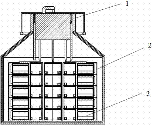
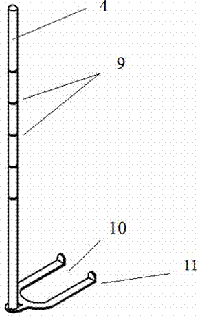
[0023] The liquid nitrogen tank of the present invention includes a tank body, a lifting cylinder 2, a freezing storage box 3, and a lifting fork 4. The lifting cylinder 2 is placed in the hollow cavity provided by the tank body, and the freezing storage box 3 is placed in the lifting cylinder 2. The box cover plate 6 is fixed on the top of the freezer box 3, and the top of the tank body is fixed with a tank cover. The fork head 10 includes a fork handle and a fork head 10 arranged at the bottom of the fork handle, and the fork handle is perpendicular to the lifting fork 4 , the fork handle is provided with a layer number scale 9, and the handle of the lifting tube 2 is provided with a hand-held mark 5, which corresponds to the layer number scale 9, and the fork head 10 provided by the lifting fork 4 is inserted into the bottom of the freezer box 3. The provided slot 8 and the provided fork hook 11 at the end of the fork 10 can hook the freezer box 3 out of the lifting tube 2 ...


PUM


Abstract

The invention discloses a liquefied nitrogen tank, which comprises a tank body, a lifting barrel, a cryopreservation box and a lifting fork, wherein the lifting barrel is arranged in a hollow cavity formed in the tank body; the cryopreservation box is arranged in the lifting barrel; a box cover plate is fixedly arranged at the top of the cryopreservation box; a tank cover is fixedly arranged at the top of the tank body; the lifting fork comprises a fork handle and a fork head arranged at the lower part of the fork handle; the fork handle is perpendicular to the lifting fork; a layer number ruler is arranged on the fork handle; a handheld mark is formed on the handle of the lifting barrel and is corresponding to the layer number ruler; the fork head of the lifting fork is inserted into a clamping slot formed in the bottom of the cryopreservation box; a fork hook arranged at the tail end of the fork head can be used for hooking the cryopreservation box out from the lifting barrel. The direct contact between the lifting barrel and room temperature air is avoided; the consummation of liquefied nitrogen is reduced; the quality of a saved sample is improved. According to the liquefied nitrogen tank, the exposure of a non-usage sample in the air is avoided; the saving quality of the sample is guaranteed; the saving time of the sample is prolonged; the sample extraction difficulty is lowered; the whole process is convenient and fast; the consummation of the liquefied nitrogen is reduced and the resource is saved.

Description

technical field [0001] The invention belongs to a liquid nitrogen tank in the technical field of ultra-low temperature preservation, in particular to a liquid nitrogen tank for a laboratory, which belongs to the innovative technology of a liquid nitrogen tank. Background technique [0002] The disadvantages of existing liquid nitrogen tanks are that the lifting cylinder is heavy and bulky as a whole, which makes extraction difficult, and it takes a long time to extract the frozen samples in the lifting cylinder. Therefore can not be accomplished conveniently and quickly. [0003] In addition, in order to extract one or two cryopreservation tubes from the existing liquid nitrogen tank, the entire lifting cylinder has to be lifted out, which affects the storage of other samples. Prolonged exposure of samples to the air has a certain negative impact on their frozen quality. [0004] In addition, during the extraction process of the existing liquid nitrogen tank, the lifting c...

Claims


Application Information

Patent Timeline
Patent Type & Authority Applications(China)
IPC IPC(8): G01N1/42
Inventor 陈智毅王华倩蔡自勇姚远洋关赛玉陈慕恩
Owner GUANGDONG UNIV OF TECH
Why Eureka
Try Eureka