
Method of realizing beamforming coordination and base station

A beamforming and cooperative base station technology, applied in the field of coordinated beamforming, can solve problems such as difficult implementation, system performance degradation, and failure to consider the impact of receiving vector performance, so as to reduce system overhead and improve system performance.

Inactive Publication Date: 2015-07-08
ZTE CORP
View PDF4 Cites 0 Cited by
  • Summary
  • Abstract
  • Description
  • Claims
  • Application Information

AI Technical Summary

Problems solved by technology

The above schemes can be divided into two types: the coordinated beamforming scheme considering the receiving vector and the coordinated beamforming scheme not considering the receiving vector. Among them, the performance of the scheme considering the receiving vector is significantly improved compared with the scheme not considering the receiving vector , however, its feedback overhead and information sharing overhead are much larger than the overhead of the scheme that does not consider the receiving vector
[0005] The traditional transmit beamforming vector design scheme based on the SLNR criterion can be implemented in a distributed manner at each base station. However, since this design method does not consider the impact of the receive vector on performance, the system performance is reduced
However, if the reception vector of each base station is considered, all cooperative base stations need to share all channel state information, which increases the overhead of the X2 interface. In short, it is relatively difficult to implement

Method used


Image

  • Method of realizing beamforming coordination and base station
  • Method of realizing beamforming coordination and base station
  • Method of realizing beamforming coordination and base station

Examples


no. 1 example

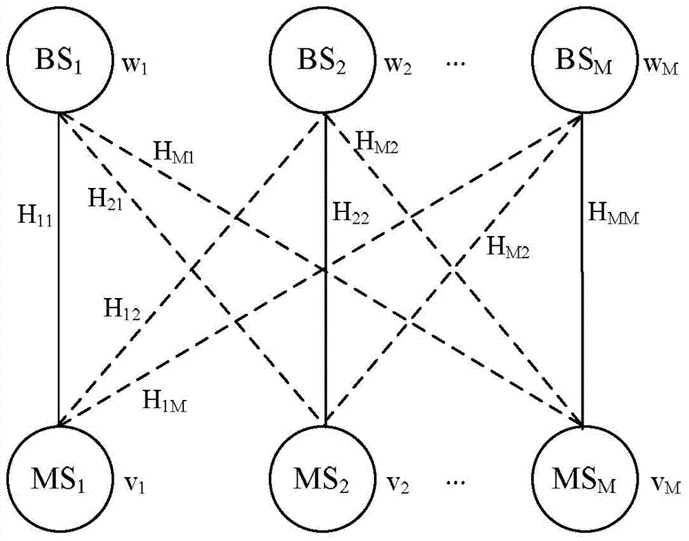
[0059] The first embodiment combines figure 1 In the downlink CoMP transmission system shown, it is assumed that in the first embodiment, the channel is static. During initialization: assuming n=1, then,

[0060] Each base station in the cooperative set initializes the transmit beamforming vector according to the existing SLNR scheme Yes and The eigenvector corresponding to the largest generalized eigenvalue of , namely w i ( n - 1 ) = max gen . eigenvector | | w i ( n - 1 ) = 1 | | ...


PUM


Abstract

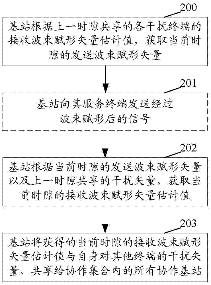
A method and base station for coordinated beamforming, comprising a base station obtaining the transmit beamforming vector of the current time slot according to the receive beamforming vector estimate, shared during the previous time slot, of each interfering terminal; the base station obtaining, according to the transmit beamforming vector of the current time slot and the interference vector of the previous time slot, the receive beamforming vector estimate of the current time slot and sharing the obtained receive beamforming vector estimate and interference vector of the current time slot. The technical solutions provided by the embodiments of the present invention take into account associated receive beamforming vectors by means of a maximum SLNR criterion-based coordinated beamforming scheme, and only two pieces of information -- receive beamforming vector estimates and interference vectors -- are shared between coordinating base stations. The technical solutions provided by the embodiments of the present invention significantly improve system performance without requiring terminal feedback of receive vector information, while significantly decreasing system overhead; at the same time, distributed implementation of coordinating base stations is achieved.

Description

technical field [0001] The invention relates to a coordinated multi-point transmission technology, in particular to a method and a base station for realizing coordinated beamforming. Background technique [0002] The joint processing technology in coordinated multi-point transmission needs to share data and channel state information among the nodes participating in the cooperation. In this way, although the system performance can be improved to the greatest extent, the throughput and delay of the backhaul link (Backhaul) are There are very high requirements, and there are strict requirements for symbol synchronization. Currently, joint processing technology is difficult to implement under the existing network architecture and standards. [0003] Coordinated beamforming is an important branch of coordinated multipoint transmission technology, which provides a compromise between Backhaul overhead and system performance. Compared with joint processing, coordinated beamforming...

Claims


Application Information

Patent Timeline
Patent Type & Authority Applications(China)
IPC IPC(8): H04B7/04H04W16/28H04W88/08
CPCH04B7/04H04B7/0617H04B7/0619H04B7/0632H04W88/08
Inventor 李斌吕刚明黄莹张国梅秦洪峰
Owner ZTE CORP
Learn More