Ultrasonic peeling device for preparing graphene

An ultrasonic peeling and graphene technology, applied in the field of graphene, can solve the problems of uneven cavitation effect, limited tank size, limited tank power density, etc., achieves good ultrasonic radiation effect and stability, improves power density, The effect of improving the peeling effect

Active Publication Date: 2015-07-15
DEYANG CARBONENE TECH
View PDF2 Cites 3 Cited by
  • Summary
  • Abstract
  • Description
  • Claims
  • Application Information

AI Technical Summary

Problems solved by technology

[0004] However, the existing technology represented by the above-mentioned patent documents still has the following defects in actual use: 1. The ultrasonic transducers are installed on the outer wall of the hexahedral tank body, and the distance between each transducer and the center of the tank body Different, resulting in uneven cavitation effect in each area of ​​the tank, which not only affects the stripping effect of graphene, but also reduces the utilization rate of graphene raw materials and the quality of graphene products
2. The ultrasonic transducer is installed on the outer wall of the tank. Due to the limited radiation distance of the ultrasonic wave, this structure limits the size of the tank. As a result, the ultrasonic stripping device using this structure is bound to be unable to prepare graphene prod

Method used


Image

  • Ultrasonic peeling device for preparing graphene
  • Ultrasonic peeling device for preparing graphene
  • Ultrasonic peeling device for preparing graphene

Examples


Example Embodiment

[0037] Example 1

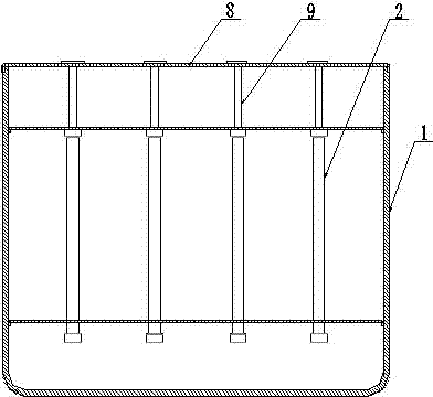
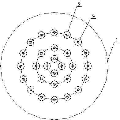
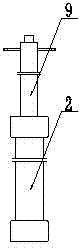
[0038] An ultrasonic stripping device for preparing graphene, comprising a tank body 1 and a plurality of ultrasonic vibrating rods 2, the plurality of ultrasonic vibrating rods 2 are vertically fixed in the tank body 1, and the plurality of ultrasonic vibrating rods 2 are placed on the same The distribution in the orthographic projection plane is circular.

[0039] In this embodiment, the multiple ultrasonic vibrating rods 2 in the tank body 1 are distributed in multiple rings in the same orthographic projection plane, and the ultrasonic vibrating rods 2 on each ring are evenly distributed. Further, all the ultrasonic vibrating rods 2 have the same height in the tank body 1, such a structure is equivalent to all the ultrasonic vibrating rods 2 being multi-ringed and uniformly arranged in the tank body 1 with a large inner diameter and a low height, that is, to increase The large tank body 1 occupies an area to achieve the purpose of large-scale stripping o...

Example Embodiment

[0044] Example 2

[0045] An ultrasonic stripping device for preparing graphene, comprising a tank body 1 and a plurality of ultrasonic vibrating rods 2, the tank body 1 is cylindrical, and its upper part is provided with a feed port 4 and an overflow port 5, and the middle part is provided with Manhole 6, the bottom is set as a slanted bottom 7, and the lower end of the slanted bottom 7 is provided with a discharge port 10; the multiple ultrasonic vibrating rods 2 are vertically fixed in the tank body 1, and the multiple ultrasonic vibrating rods 2 are distributed in multiple rings in the same orthographic projection plane.

[0046] In this embodiment, the distance between two adjacent ultrasonic vibrating rods 2 on the same ring is 40 cm, so that the ultrasonic vibrating rods 2 maintain a better radiation effect.

[0047] In this embodiment, a plurality of ultrasonic vibrating rods 2 are vertically arranged in layers in the tank body 1, and the number of ultrasonic vibratin...

Example Embodiment

[0054] Example 3

[0055] An ultrasonic stripping device for preparing graphene, comprising a tank body 1 and a plurality of ultrasonic vibrating rods 2, the plurality of ultrasonic vibrating rods 2 are vertically fixed in the tank body 1, and the plurality of ultrasonic vibrating rods 2 are There are multiple rings in the same orthographic projection plane.

[0056] In this embodiment, the distance between two adjacent ultrasonic vibrating rods 2 on the same ring is 35 cm, so that the ultrasonic vibrating rods 2 maintain a better radiation effect.

[0057] In this embodiment, the side wall and the bottom of the tank body 1 are provided with compressed air nozzles 3, and the nozzles 3 are evenly arranged in the tank body 1. When the material is stripped, the nozzles 3 spray compressed air to make the material tumble in the tank body 1. In order to improve the stripping efficiency.

[0058] Further, an air pipe connected with compressed air is welded and fixed on the inner wa...


PUM


Abstract

The invention discloses an ultrasonic peeling device for preparing graphene. The ultrasonic peeling device comprises a tank and a plurality of ultrasonic vibrating spears, wherein the plurality of ultrasonic vibrating spears are vertically fixed in the tank and are annularly distributed in the same frontal projection plane. The ultrasonic peeling device can ultrasonically irradiate the inner zone of the tank in all directions, thus achieving the purpose of remarkably increasing the power density of ultrasonic waves and shortening the peeling time.

Description

technical field [0001] The invention relates to the field of graphene, in particular to an ultrasonic stripping device for preparing graphene. Background technique [0002] Since its discovery in 2004, graphene has attracted much attention as a new type of carbon material. It is a completely sp 2 The quasi-two-dimensional crystal material composed of hybrid carbon atoms with a thickness of only one atomic layer or several single atomic layers has excellent properties such as high light transmission and electrical conductivity, high specific surface area, high strength and flexibility, etc. It is expected to be widely used in the fields of high-performance nanoelectronic devices, optoelectronic devices, gas sensors, composite materials, field emission materials and energy storage. [0003] At present, expansion ultrasonic exfoliation method is one of the main preparation methods of graphene. This method uses graphite intercalation compound as raw material, and ultrasonic e...

Claims


Application Information

Patent Timeline
IPC IPC(8): C01B31/04C01B32/19
Inventor 高华李代黎杜晓峰王兰牟瞬禹姚林
Owner DEYANG CARBONENE TECH
Why Eureka
Try Eureka