Annular tooth seam supersonic jetting nozzle

A technology of jet nozzle and ring tooth gap, which is applied in the field of supersonic jet nozzle of ring tooth gap, which can solve the problems that the nozzle material affects the area of ​​the ring gap, affects the injection flow rate, and the oxygen blowing flow is limited, so as to prevent the gun from being blocked and improve the efficiency. , the effect of high working gun position

Inactive Publication Date: 2015-07-15
CISDI ENG CO LTD +1
View PDF13 Cites 14 Cited by
  • Summary
  • Abstract
  • Description
  • Claims
  • Application Information

AI Technical Summary

Problems solved by technology

但无论是RH-KTB顶枪,还是以后开发的RH-MFB顶枪、RH-MESID顶枪、RH-PB顶枪以及中国专利200420027046.4、200610076151.0、200820174977.5、200820174973.7、200820174973.7、201110000083.0、201210346652.1、201310431081.6所涉及 The top gun or nozzle of the top gun adopts a round-hole Laval tube structure, that is, the Laval tube is generally at the center, the gas channels are distributed outside the Laval tube, and the gas channels of individual gun heads are at the center, while the Laval tube adopts a porous external Inclined distribution, all have disadvantages such as difficult manufacturing, low service life, limited flow rate of oxygen blowing, easy to block the gun during use, etc.
Chinese patent 20142044449.6 proposes annular nozzle technology, which solves the above problems, but there is a problem that the expansion of the nozzle material after heating affects the area of ​​the annular seam and thus affects the injection flow rate

Method used


Image

  • Annular tooth seam supersonic jetting nozzle
  • Annular tooth seam supersonic jetting nozzle
  • Annular tooth seam supersonic jetting nozzle

Examples


Embodiment Construction

[0042] The implementation of the present invention will be illustrated by specific specific examples below, and those skilled in the art can easily understand other advantages and effects of the present invention from the contents disclosed in this specification.

[0043] The directions mentioned in this embodiment take the direction from back to front as the spraying direction.

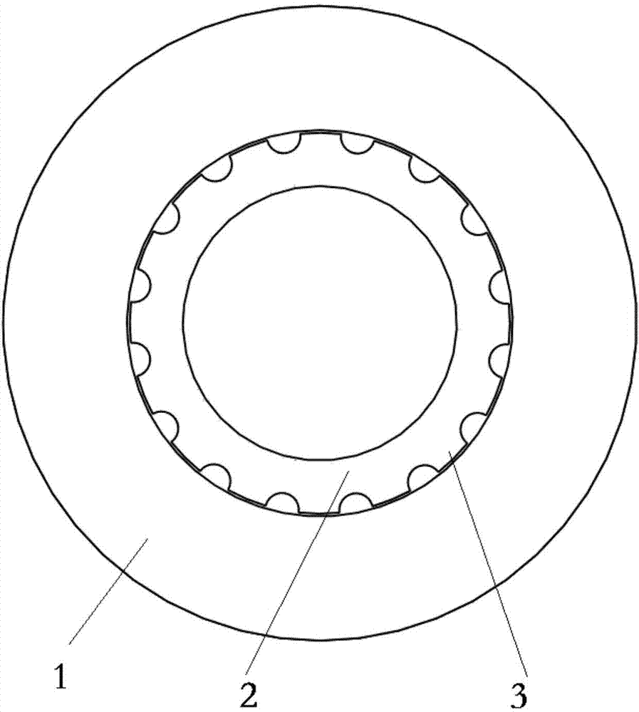
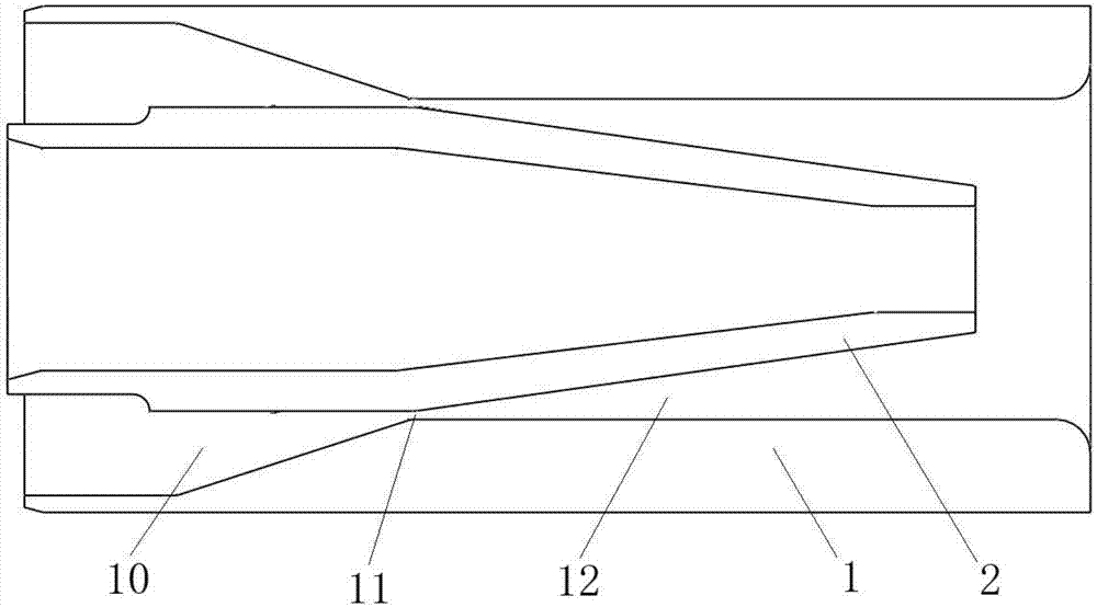
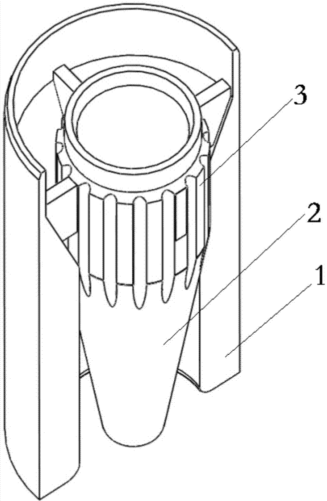
[0044] Such as Figure 1 to Figure 3 As shown, the present invention provides a ring-tooth supersonic jet nozzle, comprising a coaxially arranged hollow core tube 2 and a variable-section outer tube 1, the hollow core tube 2 is located inside the outer tube 1, and the inner surface of the outer tube 1 is aligned with the hollow Between the outer contour surfaces of the core tube 2, three sections of variable-section passages are formed in sequence along the axial direction: the annular constriction section 10, the throat section 11 and the annular expansion section 12, wherein the cross section of th...


PUM


Abstract

The invention discloses an annular tooth seam supersonic jetting nozzle. An annular pipe airflow channel is composed of a hollow core pipe and an outer pipe with the variable cross-section and provided with a contraction acceleration segment with the annular cross section and an expanding acceleration segment with the annular cross section. A transition segment of an annular tooth cross section is connected with the contraction segment and the expanding segment, gas of the certain pressure and flow can be accelerated to be at supersonic speed, and supersonic jet is formed at an outlet of the nozzle. When the annular tooth seam supersonic jetting nozzle is applied to an RH vacuum refining furnace top gun, oxygen blowing decarbonization, oxygen blowing temperature increasing and powder spraying desulfuration can be achieved for molten steel inside a vacuum chamber on the vacuum condition, and gas is blown to the vacuum chamber on the non-vacuum condition for baking and heating to remove cold steel; when the annular tooth seam supersonic jetting nozzle is applied to an electric furnace wall gun, supersonic airflow can cut scraped steel and spray carbon powder to form foaming slags; when the annular tooth seam supersonic jetting nozzle is applied to a blast furnace, long-distance pulverized coal spraying can be achieved. When the annular tooth seam supersonic jetting nozzle is applied to an industrial heating furnace, high-power super-long flame heating can be achieved; when the annular tooth seam supersonic jetting nozzle is applied to a steam jetting vacuum pump, high-flow air exhaust can be achieved.

Description

technical field [0001] The invention relates to a jetting device used for generating supersonic airflow in the metallurgical industry, in particular to a supersonic jet jet nozzle with ring tooth gaps. Background technique [0002] Supersonic jets are widely used in the metallurgical industry, such as oxygen lances in top-blown converters, top lances in RH vacuum refining, etc. 但无论是RH-KTB顶枪,还是以后开发的RH-MFB顶枪、RH-MESID顶枪、RH-PB顶枪以及中国专利200420027046.4、200610076151.0、200820174977.5、200820174973.7、200820174973.7、201110000083.0、201210346652.1、201310431081.6所涉及 The top gun or nozzle of the top gun adopts a round-hole Laval tube structure, that is, the Laval tube is generally at the center, the gas channels are distributed outside the Laval tube, and the gas channels of individual gun heads are at the center, while the Laval tube adopts a porous external Inclined distribution, all have disadvantages such as difficult manufacturing, low service life, limited flow rate of oxygen blowing, a...

Claims


Application Information

Patent Timeline
Patent Type & Authority Applications(China)
IPC IPC(8): C21C7/10
Inventor 刘向东艾磊王翔黄其明彭晓华
Owner CISDI ENG CO LTD
Why Eureka
Try Eureka