Assembled semi-rigid wood structure joint

A semi-rigid, wood structure technology, used in building components, building structures, earthquake resistance, etc., can solve the problem of limited bending bearing capacity and rotational stiffness of joints, which can only be used in simply supported or hinged situations, and difficult to design, construct and install. Competency and other issues, to achieve the effect of reducing maintenance and repair costs, high practical value and economic value, and good bearing capacity

Inactive Publication Date: 2015-07-15
NANJING UNIV OF TECH
11 Cites 8 Cited by

AI-Extracted Technical Summary

Problems solved by technology

Taking the commonly used pin-bolt connection as an example, usually the pin-bolt connection is mainly borne by the bending bearing of fasteners such as pins and the pressure bearing of wood pin grooves. If the number of fasteners is small, the flexural bearing capacity and rotational The rigidity is limited, and it can only be used in simply supported or hinged situations; if the number of fasteners is large, it is easy to cause the joi...

Abstract

The invention discloses an assembled semi-rigid wood structure joint. The assembled semi-rigid wood structure joint comprises a component I, a component II, a bending connecting piece, a shear connecting piece, an assembling piece, a steel cushion plate and connecting bolts, wherein the component I is a wood component, the bending connecting piece and the shear connecting piece are fixedly arranged at the end portion of the component I by adopting a steel plate implanting manner, the bending connecting piece and the shear connecting piece are T-shaped steel, the surfaces of the parts thereof implanted into the wood member are vulcanized with rubber layers, the end portion of the component I is pre-grooved at a steel plate implanting position, and the bending connecting piece and the shear connecting piece are connected through the connecting bolts and the assembling piece; the end portion of the component I can be connected with the side surfaces and the end portion of the component II or can be connected with a concrete foundation. The joint disclosed by the invention has higher bending capacity, joint rigidity, energy dissipation capacity and ductility performance. The joint not only can guarantee the structure stability under small earthquakes, but also can realize the prevention of large deformation of the structure under large earthquakes and control structure damages, and realizes ideal effects of high bearing capacity, high energy dissipation capacity and high ductility.

Application Domain

Technology Topic

Image

  • Assembled semi-rigid wood structure joint
  • Assembled semi-rigid wood structure joint
  • Assembled semi-rigid wood structure joint

Examples

  • Experimental program(1)

Example Embodiment

[0031] The present invention will be further described below in conjunction with the accompanying drawings and specific embodiments.
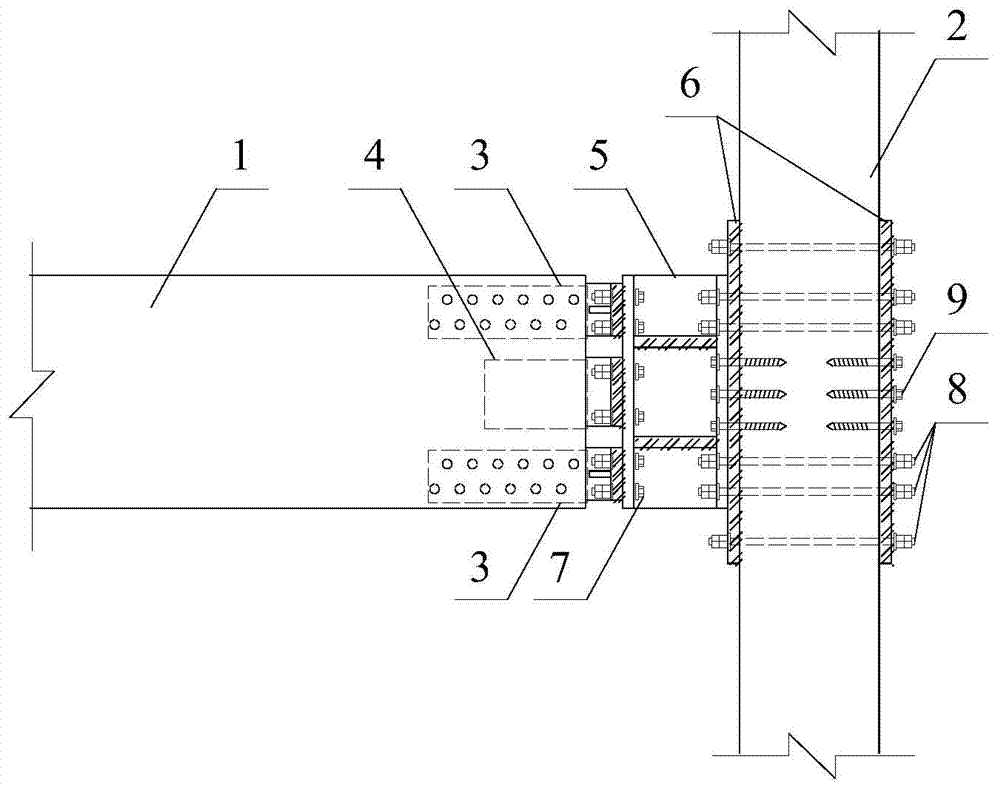
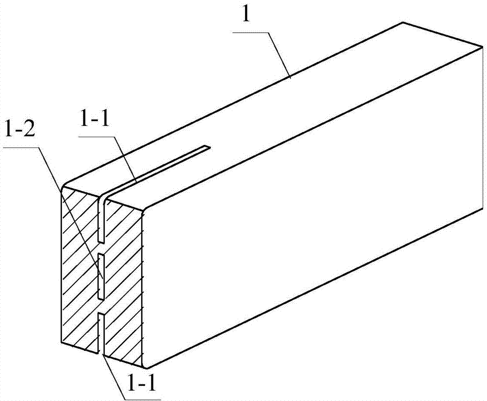
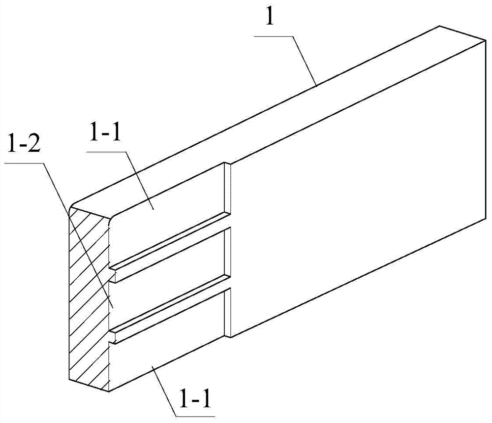
[0032] like Figure 1-8 Shown: a prefabricated semi-rigid wood structure node, including component one 1, component two 2, bending connector 3, shear connector 4, assembly 5, steel backing plate 6 and connecting bolt 7;
[0033] The member one 1 is a wooden member, the bending connector 3 and the shear connector 4 are fixed to the end of the member one 1 by planting steel plates, and the bending connector 3 and the shear connector 4 are T-shaped steel 3-1, the rubber layer is vulcanized on the surface of the implanted wooden component part, and the end of component 1 is pre-grooved on the planting steel plate, and the pre-grooving includes pre-grooving 1-1 on the top and bottom of the component and pre-grooving 1-1 in the center of the component. 2, respectively corresponding to the bending connector 3 and the shear connector 4, the bending connector 3 and the shear connector 4 are connected to the assembly 5 through the connecting bolt 7, and the bending connector 3 is provided with a bending connector wing Edge bolt holes 3-3 and T-shaped steel stiffeners 3-4, there is a weld 3-5 between the T-shaped steel stiffeners 3-4 and T-shaped steel 3-1, and the shear connector 4 is provided with a shear The flange bolt hole 4-1 of the connector, the assembly flange bolt hole 5-1 is provided on the assembly part 5;
[0034] When the end of the component one 1 is connected to the side of the component two 2, the assembly part 5 is fixed on the component two 2 through the steel backing plate 6, the anchor bolt 8, and the anchor screw 9;
[0035] When the ends of the component one 1 and the component two 2 are connected to each other, the structure of the end of the component two 2 is the same as that of the above component one 1, and the fitting 5 at the end of the component one 1 is connected to the end of the component two 2 The assembly part 5 is a whole, and the component one 1 and the component two 2 are connected as a whole, and the assembly part 5 is also provided with a steel pipe stiffening plate 10;
[0036] When the component two 2 is a concrete foundation 12, the end of the component one 1 is vertically installed on the top surface of the concrete foundation 12, and the assembly 5 at the end of the component one 1 passes through the steel backing plate 6, the anchor bolt 11 and the concrete foundation. 12 fixed.
[0037] The thickness of the rubber layer is 1-5 mm, and the rubber material is styrene-butadiene rubber, natural rubber or mixed rubber. In order to further improve the bonding performance and to facilitate the installation of self-tapping wood screws, the bending connector 3 is provided with openings 3-2 in the web of the bending connector at intervals. The bending connector 3 and the shear connector 4 adopt double webs, so as to further increase the bonding area and provide greater bearing capacity. The assembly part 5 adopts I-beam or steel pipe; when the component size is large, in order to facilitate assembly and adapt to the different expansion and contraction of steel and wood at the same time, the bolt holes used to connect it with the bending connector 3 adopt waist round holes, and the rest are all Round holes are used. In order to prevent the positive tensile damage of the glue layer of the planted steel plate after being stressed, the ends of the first component 1 and the second component 2 are reinforced with self-tapping wood screws passing through the wood component and the planted steel plate. The wood components are combined by double or multiple components cut along the central plane of the planting steel plate, which can further simplify the process of planting the steel plate, and the double or multiple components can be assembled by self-tapping wood screws or bolts; The steel plate part can be grooved, and the groove depth is less than 1/2 of the thickness of the planted steel plate.
[0038] It should be pointed out that those skilled in the art can make some improvements and modifications without departing from the principle of the present invention, and these improvements and modifications should also be regarded as the protection scope of the present invention. All components that are not specified in this embodiment can be realized by existing technologies.

PUM

PropertyMeasurementUnit
Thickness1.0 ~ 5.0mm
tensileMPa
Particle sizePa
strength10

Description & Claims & Application Information

We can also present the details of the Description, Claims and Application information to help users get a comprehensive understanding of the technical details of the patent, such as background art, summary of invention, brief description of drawings, description of embodiments, and other original content. On the other hand, users can also determine the specific scope of protection of the technology through the list of claims; as well as understand the changes in the life cycle of the technology with the presentation of the patent timeline. Login to view more.

Similar technology patents

Lightweight aluminum alloy template and preparation method thereof

PendingCN114561574AImprove alloy strengthGood carrying capacityNano zinc oxideCarbide silicon
Owner:重庆新久融科技有限公司

Piezoelectric actuation micro-nano deflection platform

PendingCN114785189AProtective Displacement AmplificationGood carrying capacityPiezoelectric/electrostriction/magnetostriction machinesPhysicsFixed hinge
Owner:GUANGZHOU UNIVERSITY

Switch cabinet

Owner:GUANGDONG POWER GRID CO LTD +1

Classification and recommendation of technical efficacy words

  • Good carrying capacity
  • Reduce stress concentration

Road repairing device for civil engineering

ActiveCN111364341AAvoid road congestionGood carrying capacityRoads maintainenceCamStructural engineering
Owner:邵阳公路桥梁建设有限责任公司

Tire type coupling

Owner:镇江市润州联轴器厂

Front plate assembly for dump truck

Owner:LIUZHOU JIELONG AUTO PARTS MFG

Flexible heart valve

InactiveUS20050096739A1Reduce stress concentrationHeart valvesProsthesisCommissure
Owner:EDWARDS LIFESCIENCES CORP
Why Eureka
Try Eureka