Oil baffle plate installation welding mode oil bottom case assembly

A technology for installing welding and oil baffles, applied in the direction of oil pan, engine components, lubricating parts, etc., can solve the problems of oil pan cracking, adding extra load, weakening the strength of oil pan, etc., and achieve the elimination of tensile stress Effect

Inactive Publication Date: 2015-07-15
GUANGXI YUCHAI MASCH CO LTD
View PDF7 Cites 5 Cited by
  • Summary
  • Abstract
  • Description
  • Claims
  • Application Information

AI Technical Summary

Problems solved by technology

[0004] Under the action of gas force, the skirt of the body produces periodic expansion deformation, and the oil pan follows the skirt of the body to produce the same periodic expansion deformation, and the closer it is to the body, the greater the deformation. The welding of the oil baffle and the side of the oil pan results in Increased oil plate stiffness
The deformation of the body skirt and the lateral stiffness of the oil baffle tear the side of the oil pan in the opposite direction. At the same time, welding thermal stress and welding tensile stress will be generated after the oil baffle is welded to the oil pan, which weakens the strength of the oil pan, and the engine oil Impacting the oil baffle will add additional load to the oil pan weld, causing the oil pan to pull apart from the weld closest to the oil pan flange face

Method used


Image

  • Oil baffle plate installation welding mode oil bottom case assembly
  • Oil baffle plate installation welding mode oil bottom case assembly
  • Oil baffle plate installation welding mode oil bottom case assembly

Examples


Embodiment 1

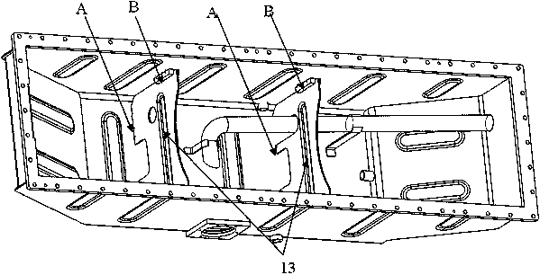
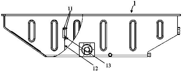
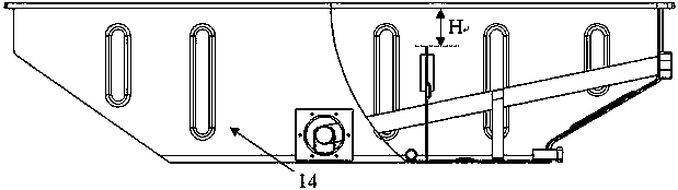
[0022] Embodiment 1, an oil pan assembly in which an oil baffle is installed and welded, which includes a pressure block, an oil pan body, and an oil baffle. The pressure block (11) is connected to the side of the oil sump body (14) by segmental welding to fix the oil baffle (12). The oil baffle (12) is clamped in the pressure block (11) of the oil pan body (14) and welded to the bottom surface of the oil pan body (14) in sections, and the oil baffle (12) ) is far away from the flange surface of the oil pan body (14) and is provided with a transverse reinforcing rib (13). The side of the oil pan body (14) is designed with a pressure block (11) for fixing the oil baffle (12). The pressure block (11) is used to clamp the oil baffle (12), and only the pressure block (11) The contact surface with the oil pan and the contact surface with the oil baffle (12) are not welded. The distance between the oil baffle plate (12) and the flange surface of the oil pan body (14) is relatively...

Embodiment 2

[0023] Example 2, such as Figure 1 to Figure 3 , which shows a schematic diagram of an oil pan assembly (1) according to a specific embodiment of the present invention.

[0024] like figure 1 and figure 2 As shown, an oil pan assembly in the way of installing and welding the oil baffle includes a pressure block (11), an oil baffle (12) and an oil pan body (14). The pressure block (11) is connected to the side of the oil pan body (14) by segmental welding, and only the contact side of the pressure block (11) and the oil pan body (14) is welded, and is in contact with the oil baffle plate (12) The edges are not welded. in image 3 The segmented welding area B is shown in , and it should be noted that the welding position is only an example, and those skilled in the art can determine the welding range according to different sizes of the oil baffle plate and the oil pan body. Since there is no welding at the contact edge between the briquetting block (11) and the oil baffle...


PUM


Abstract

The invention discloses an oil baffle plate installation welding mode oil bottom case assembly. An oil baffle plate and a press block used for fixing the oil baffle plate are designed on the side surface of an oil bottom case body, a great distance from the top surface of the oil baffle plate to the flange surface of the oil bottom case body exits, the oil baffle plate is clamped by the press block and is not in contact with the wall surface of the oil bottom case body, and is in segmented welding connection with the bottom surface of the oil bottom case body, the oil baffle plate is transversely provided with a buffer reinforcing rib, an oil sucking disc supporter arranged on the oil baffle plate is in an arched door shape, and the oil baffle plate is not in contact with an oil sucking pipe. The oil baffle plate is clamped by the press block, the height of the oil baffle plate is reduced, the oil bottom case body adopts a segmented welding connecting mode, the tensile stress generated after the oil baffle plate and the side surface of the oil bottom case body are welded is fundamentally eliminated, and in addition, the force, caused by engine oil impact, transferred to an oil bottom case bottom surface welding seam is reduced, so that the reliability and the durability of the oil bottom case assembly are improved.

Description

technical field [0001] The invention relates to the field of engine accessories, in particular to an oil pan assembly of an engine oil baffle installed and welded. Background technique [0002] The oil sump is located at the bottom of the engine, and its function is to close the crankcase as the casing of the oil storage tank, prevent impurities from entering, and collect and store the lubricating oil flowed back by the friction surfaces of the diesel engine. An oil baffle is installed inside the oil pan to avoid the shock and splash of the oil surface caused by the bumping of the diesel engine, and to facilitate the precipitation of lubricating oil impurities. [0003] In the prior art, for stamped oil pans, generally the height of the oil baffle plate is relatively close to the flange surface of the oil pan, and the surface of the oil baffle plate in contact with the oil pan is directly welded to the oil pan. The oil baffle and the side of the oil pan are generally segmen...

Claims


Application Information

Patent Timeline
Patent Type & Authority Applications(China)
IPC IPC(8): F01M11/00
CPCF01M11/0004
Inventor 韩闪闪卢祥林张健王利乐
Owner GUANGXI YUCHAI MASCH CO LTD
Why Eureka
Try Eureka