
Workpiece holder in ultrasonic testing equipment and positioning method

A workpiece fixture and testing equipment technology, which is applied in the direction of material analysis, measuring device, and instrument using sonic/ultrasonic/infrasonic waves, can solve the problem of inability to realize batch testing, and achieve the effect of ensuring accuracy and improving testing efficiency.

Inactive Publication Date: 2015-07-15
SHANGHAI HIWAVE PRECISION INSTR CO LTD
View PDF4 Cites 6 Cited by
  • Summary
  • Abstract
  • Description
  • Claims
  • Application Information

AI Technical Summary

Problems solved by technology

The American OKOS company also has a corresponding product launch. Although this product has a workpiece fixture, it cannot achieve batch testing.

Method used


Image

  • Workpiece holder in ultrasonic testing equipment and positioning method
  • Workpiece holder in ultrasonic testing equipment and positioning method
  • Workpiece holder in ultrasonic testing equipment and positioning method

Examples


Embodiment 1

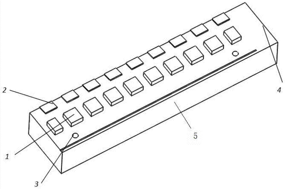
[0030] Such as figure 1 As shown, this embodiment provides a multi-station workpiece fixture in ultrasonic testing equipment, the fixture includes a multi-station workpiece clamping structure 1, a workpiece fixing structure 2, a fixture bottom positioning structure 3, a fixture numbering area 4 and a base 5, of which:

[0031] The multi-station workpiece clamping structure 1, that is, a plurality of bosses arranged in the middle of the base 5, is used to fix the left and right sides of the workpiece to be tested, so as to realize the batch detection of the workpiece to be tested and improve the detection efficiency. efficiency;

[0032] The workpiece fixing structure 2, that is, a plurality of elastic fixing pieces arranged at the tail of the base 5, is used to resist the tail of the workpiece to be measured and cooperate with the workpiece clamping structure 1 to ensure that the workpiece to be measured is stable and does not move;

[0033] The positioning structure 3 at th...

Embodiment 2

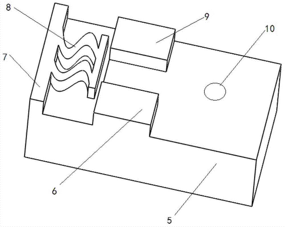
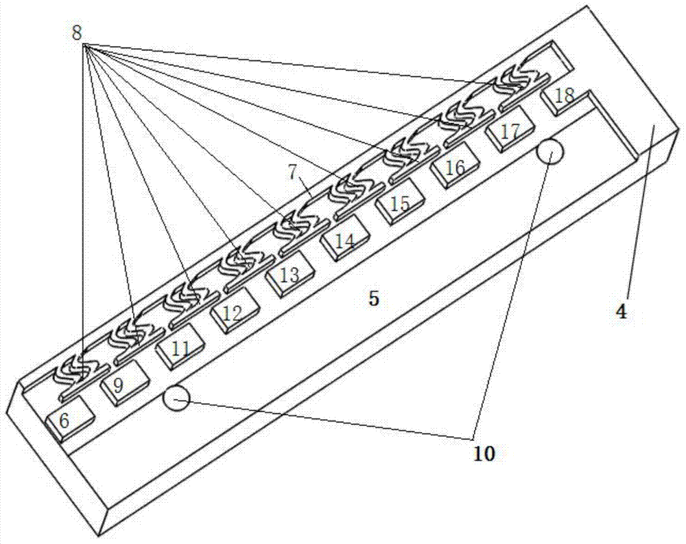
[0039] Such as figure 2 As shown, this embodiment provides another single-station workpiece fixture in ultrasonic testing equipment. The workpiece fixture includes: a base 5, fixed bosses 6, 9 arranged in the middle of the base 5, arranged on the The fixed boss 7 at the tail of the base 5, the supporting spring 8, and the positioning hole 10; wherein:

[0040] The base 5 is a cuboid, and the surface of the base 5 is larger than the lower surface of the workpiece to be measured; the fixed bosses 6, 9 are arranged in the middle of the base 5 and distributed symmetrically; the fixed bosses 6 and The height of 9 is 5mm; the fixed boss 7 is arranged on the tail of the base 5, and the height of the fixed boss 7 is the same as that of the fixed bosses 6 and 9; one end of the support spring 8 is fixed on the The upper and other ends of the fixed boss 7 are free; the positioning hole 10 is set at the center of the base 5 for overall fixing of the workpiece fixture.

[0041] When usi...


PUM

PropertyMeasurementUnit
heightaaaaaaaaaa

Abstract

The invention discloses a workpiece holder in ultrasonic testing equipment and a positioning method. The workpiece holder comprises a base and a workpiece holding structure, a workpiece fixing structure, a holder bottom positioning structure and a holder number area, wherein the workpiece holding structure, the workpiece fixing structure, the holder bottom positioning structure and the holder number area are arranged on the base; the workpiece holding structure is arranged at the middle part of the base; the workpiece fixing structure is arranged at a workpiece holding place of the base; the holder bottom positioning structure is a positioning hole which is formed in the bottom of the base; the holder number area is an area which is obligated at one end of the base. According to the workpiece holder in the ultrasonic testing equipment and the positioning method, the effective positioning of the workpiece welding surfaces in the horizontal and vertical directions and the batch detection of the workpieces can be realized and the detection efficiency is improved; meanwhile, corresponding workpiece holders are provided to the workpieces with different shapes, so that the accuracy of the detection is ensured; through the accurate positioning of the workpieces, more useful information can be obtained.

Description

technical field [0001] The invention relates to a fixture in the field of ultrasonic testing of electric contact welding quality, in particular to a workpiece fixture and a positioning method in ultrasonic testing equipment. Background technique [0002] Ultrasonic testing is a common method in non-destructive testing, and it is also a common testing method for weld quality. Most of the ultrasonic testing is to judge the internal gap and material distribution of the workpiece through the ultrasonic transmission intensity or reflection intensity of the workpiece to be tested. The welding quality of electrical contacts is detected and judged by detecting the reflection intensity of ultrasonic waves on the welding surface. When ultrasonic testing equipment detects the welding quality of electrical contacts, the probe detects the distribution and size of defects through surface scanning. Since the ultrasonic reflection intensity is closely related to the distance from the refle...

Claims


Application Information

Patent Timeline
Patent Type & Authority Applications(China)
IPC IPC(8): G01N29/26
Inventor 肖东刘伟利张国方裘揆陈乐生
Owner SHANGHAI HIWAVE PRECISION INSTR CO LTD
Learn More