High-current power supply relay

A high-current power supply and relay technology, applied in the direction of electromagnetic relays, relays, detailed information of electromagnetic relays, etc., can solve the problems of large overall volume, shortened life of relays, and weak carrying capacity, so as to reduce electrical corrosion, avoid frame size, and prolong The effect of service life

Active Publication Date: 2015-07-15
温州北方电子机械有限公司
View PDF6 Cites 11 Cited by
  • Summary
  • Abstract
  • Description
  • Claims
  • Application Information

AI Technical Summary

Problems solved by technology

The DC contactor adds a ceramic piece on the contact piece between the two contacts, forcing the arc to extend to 2 to 3 times the original length in the same space, and extinguishing the arcs before they are connected to each other. The reverse on-off capability of the DC contactor is greatly improved, but the invention adopts the method of increasing the gap for arc suppression. The larger the running gap, the larger the overall volume, and at the same time, it does not grab the arc from the source of the arc. , the arc always exists, and the carrying capacity is weak
[0006] At present, there is an urgent need for a relay with long life, reliable operation, high voltage and high current, and can solve the problem of arc corrosion of the contacts when the relay is closed, which shortens the life of the relay.

Method used


Image

  • High-current power supply relay
  • High-current power supply relay
  • High-current power supply relay

Examples


Embodiment Construction

[0040] The embodiments of the present invention will be described in detail below with reference to the accompanying drawings, but the present invention can be implemented in many different ways defined and covered by the claims.

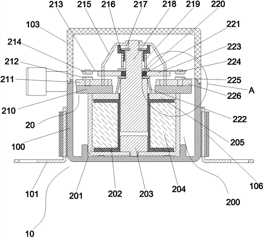
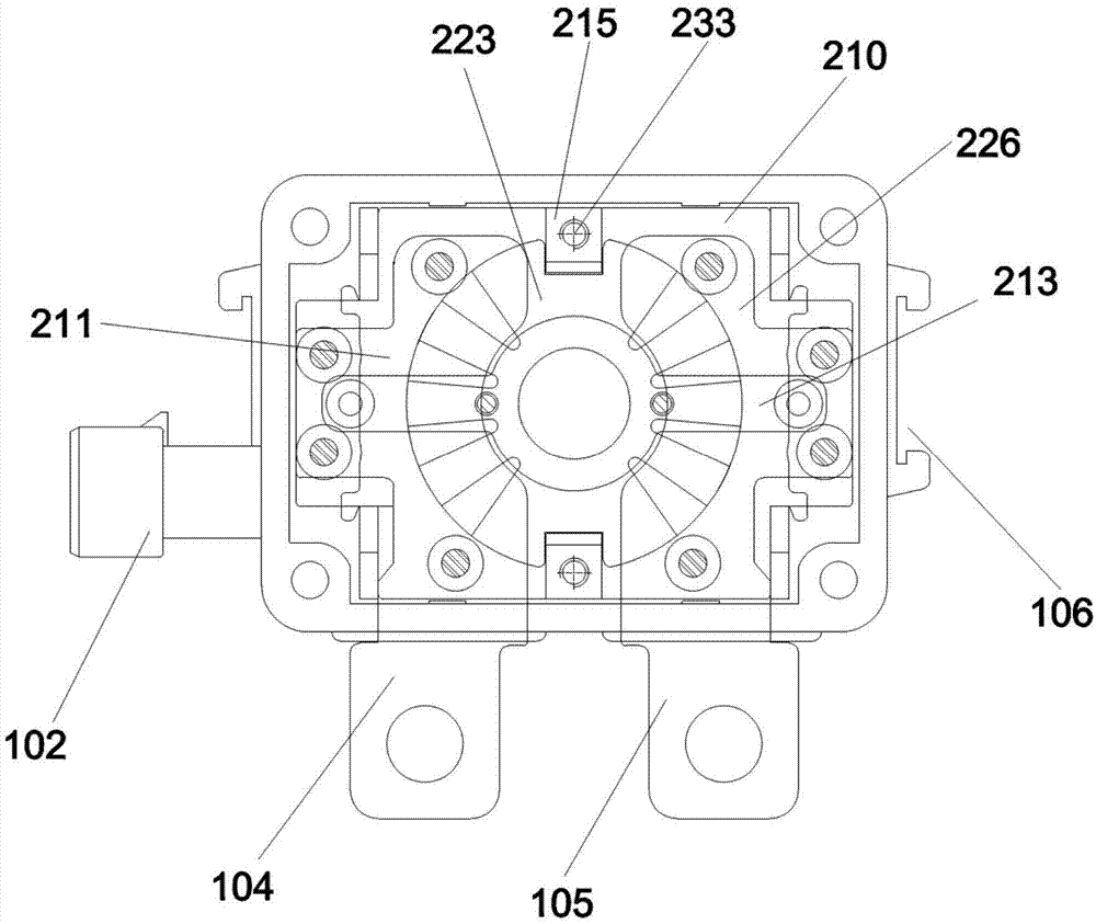
[0041] refer to Figures 1 to 10 ,Such as figure 1 A high-current power relay shown includes a casing 10, an electromagnetic drive mechanism 200 and an electrical contact member 20, the casing 10 includes a lower case 100; the electromagnetic drive mechanism 200 is arranged in the lower case 100, and includes a coil frame 202 and a movable magnetically permeable metal core 218 disposed in the coil frame 202 .

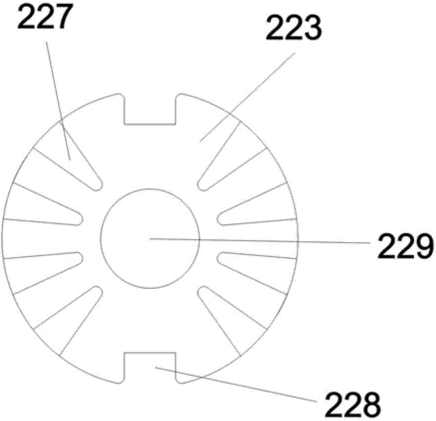
[0042] The electromagnetic drive mechanism 200 is provided with a bakelite board 210, and the electrical contact member 20 includes a first static contact piece 211 and a second static contact piece 226 arranged on both sides of the bakelite board 210, and is sleeved on the movable guide. The movable contact piece 223 on the magnetic metal ...


PUM


Abstract

The invention discloses a high-current power supply relay which comprises a casing, an electromagnetic driving mechanism and an electric contact assembly, wherein the casing comprises a lower casing; the electromagnetic driving mechanism comprises a coil rack and movable magnetic-conductive metal cores arranged in the coil rack, and a bakelite plate is arranged on the electromagnetic driving mechanism; the electric contact assembly comprises a first static contact piece and a second static contact piece which are arranged on two sides of the bakelite plate as well as a movable contact piece arranged on the movable magnetic-conductive metal core in a sleeving manner, a stainless steel connecting piece is arranged on the movable contact piece, a first movable contact and a second movable contact are arranged at two ends of the stainless steel connecting piece respectively, and a first static contact and a second static contact are respectively arranged on the first static contact piece and the second static contact piece correspondingly arranged below the first movable contact and the second movable contact. The movable contacts are adopted to be contacted with the static contacts in advance, so that the current is conducted in advance for arc extinguishing, and then the movable contact piece is contacted with the static contact piece to realize arcless contact; in a short time when the movable contact piece is separated from the static contact piece, the movable contacts are still contacted with the static contacts, that is, separation is delayed, and an arc extinction function is performed likewise, so that prolonging of the service life as well as reliable and safe working performance of the movable contact piece and the static contact piece is guaranteed.

Description

technical field [0001] The invention relates to a relay, in particular to a high-current power supply relay. Background technique [0002] The relay is an electric control device, which is an electrical appliance that causes the controlled quantity to undergo a predetermined step change in the electrical output circuit when the change of the input quantity (excitation quantity) meets the specified requirements. It has an interactive relationship between the control system (also known as the input loop) and the controlled system (also known as the output loop). Usually used in automatic control circuits, it is actually an "automatic switch" that uses a small current to control the operation of a large current. Therefore, it plays the role of automatic adjustment, safety protection, and conversion circuit in the circuit. Relay is an automatic switching element with isolation function. It is widely used in remote control, telemetry, communication, automatic control, mechatron...

Claims


Application Information

Patent Timeline
Patent Type & Authority Applications(China)
IPC IPC(8): H01H50/54H01H9/38
CPCH01H50/541
Inventor 王传富王庄毅
Owner 温州北方电子机械有限公司
Why Eureka
Try Eureka