Electrical cabinet and heat dissipation control method thereof

A control method and technology of electrical cabinets, applied in the electrical field, can solve the problems of easily damaged components, cost-effectiveness, and system paralysis, and achieve the effects of improving cooling efficiency, reducing losses, and preventing failures

Active Publication Date: 2015-07-15
HAONONGYI E COMMERCE CO LTD
View PDF5 Cites 17 Cited by
  • Summary
  • Abstract
  • Description
  • Claims
  • Application Information

AI Technical Summary

Problems solved by technology

[0005] 1. Adopt the scheme of installing a fan in the electrical cabinet. Since the fan will vibrate when it is working, this vibration will be transmitted directly to the electrical components inside it through the cabinet body. When various electrical components are in a vibrating state for a long time, their internal The components are easily damaged, which affects the service life. On the other hand, various connecting lines and contacts are also disengaged due to long-term vibration, causing the entire system to fail. Therefore, there are problems in the scheme of using an internal fan;
[0006] 2. The electrical cabinet is generally placed in the electrical control room. If the electrical control room is not equipped with an air conditioner, the temperature of the entire electrical control room will be very high, especially in summer, due to the high temperature of the external air, the fan in the electrical cabinet has to work for a long time; In addition, if an air conditioner is installed in the electrical control room, most of the cold air generated by the air conditioner is building energy consumption, that is, the air in the entire electrical control room needs to be cooled, so the energy consumption will be high, which is not cost-effective;
[0007] 3. The control core in the electrical cabinet: the controller does not have a separate heat dissipation structure. Once the controller fails due to untimely heat dissipation, it will paralyze the entire system and cause immeasurable losses
[0008] Because there are above-mentioned technical problems in prior art, affect use, therefore must improve

Method used


Image

  • Electrical cabinet and heat dissipation control method thereof
  • Electrical cabinet and heat dissipation control method thereof
  • Electrical cabinet and heat dissipation control method thereof

Examples


Embodiment 1

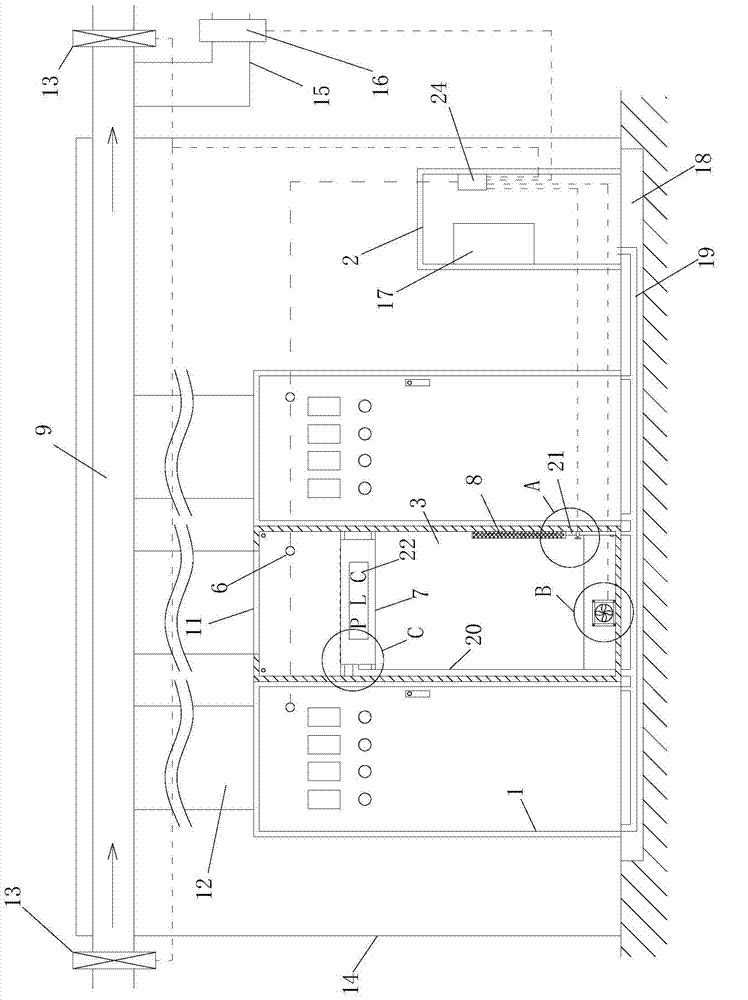
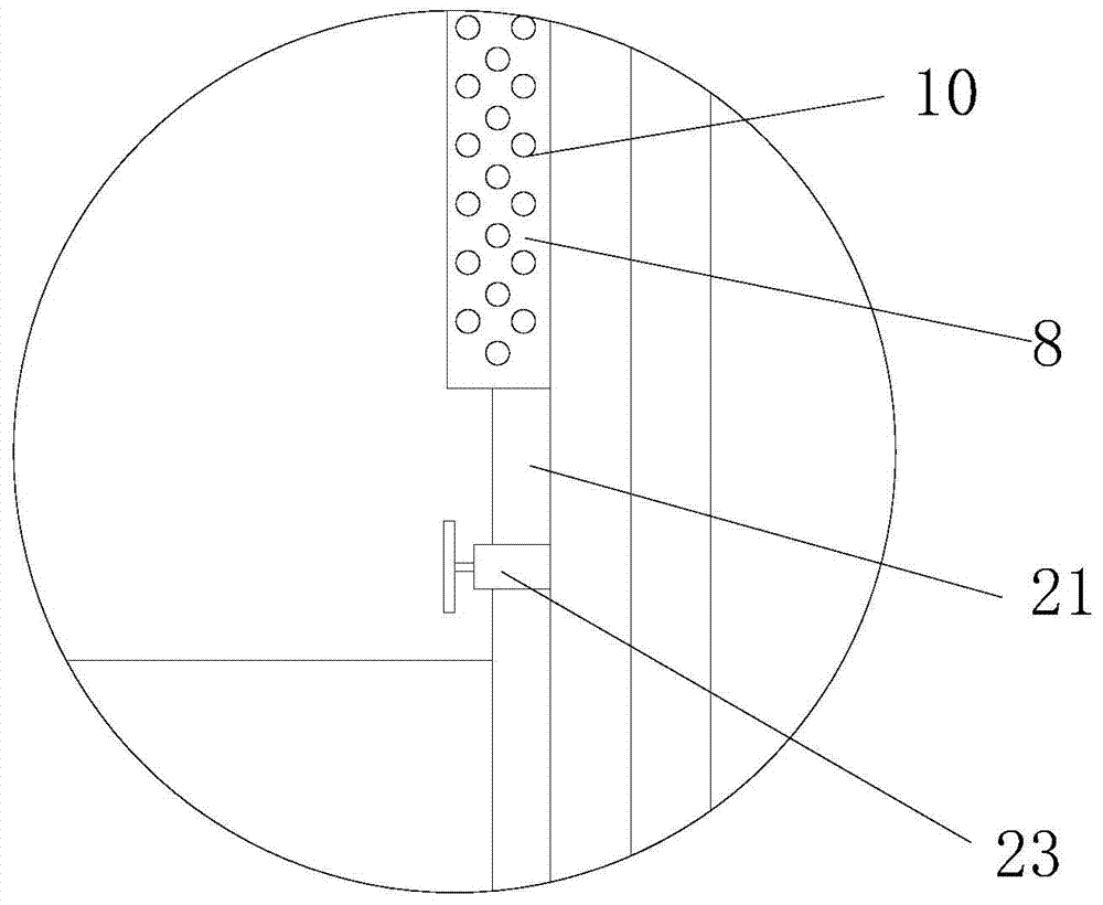
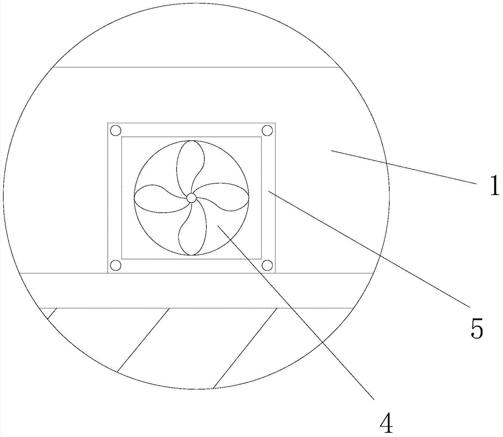
[0029] like figure 1 , 2 , 3, and 4, the electrical cabinet described in this embodiment includes several cabinets 1 and an air-conditioning cabinet 2 arranged side by side, wherein the number of cabinets 1 is generally 3-8 in a row, and of course it can be changed According to the actual situation, there is a mounting plate 3 for installing electrical components in the cabinet 1, an air inlet 4 is provided at the bottom of the cabinet 1, a fan 5 is provided on the air inlet 4, and a fan 5 is installed in the cabinet 1. There is a temperature sensor 6; a controller installation chamber 7 is arranged on the mounting plate 3, and the upper part of the controller installation chamber 7 has an overflow hole 25, and a cold air cover 8 is arranged on the inner wall of the cabinet body 1, and the cold air cover 8 The surface is covered with air outlet holes 10; an air duct 9 with both ends open is provided above the cabinet body 1, and the air outlet 11 at the top of each cabinet bo...

Embodiment 2

[0048] like Figure 5 As shown, the electrical cabinet described in this embodiment is different from Embodiment 1 in that the bottom surface of the air duct 9 is a structure with a high middle and low sides. Such a scheme can prevent rainwater from entering the air duct, so that rainwater cannot live in the center flow Prevent rainwater from entering the cabinet body 1.

[0049] Also can be provided with some rows of water retaining rods on the bottom surface of air duct 9 and carry out waterproofing.

Embodiment 3

[0051] like Figure 6 As shown, the electrical cabinet described in this embodiment includes several cabinets 1 and an air-conditioning cabinet 2 arranged side by side, wherein the number of cabinets 1 is generally 3-8 in a row, and of course there can be more, depending on the actual situation Depending on the situation, a mounting plate 3 for installing electrical components is provided in the cabinet body 1, an air inlet 4 is provided at the lower part of the cabinet body 1, a fan 5 is provided on the air inlet port 4, and a temperature sensor 6 is also provided in the cabinet body 1 ; A controller installation chamber 7 is provided on the installation plate 3, and the upper part of the controller installation chamber 7 has an overflow hole 25, and a cold air cover 8 is provided on the inner wall of the cabinet body 1, and the surface of the cold air cover 8 is covered with outlets. Air holes 10; an air duct 9 with open ends is provided above the cabinet body 1, and the air...


PUM


Abstract

The invention discloses an electrical cabinet. The electrical cabinet comprises cabinet bodies and a cold air cabinet. An installation plate for installing electrical elements is arranged in each cabinet body, and a controller installation chamber is formed in each installation plate. An air channel with two open ends is formed above the cabinet bodies, air outlets in the tops of the cabinet bodies are communicated with the air channel through heat dissipation tubes, and the two ends of the air channel are located outside an electrical control chamber. An air conditioner is arranged in the cold air cabinet. A groove is formed in the floor of the electrical control chamber. The bottom of the cold air cabinet is connected with a cold air pipe. A first pipeline and a second pipeline are arranged in each cabinet body, the first pipelines are communicated between the cold air pipe and the controller installation chambers, the second pipelines are communicated between the cold air pipe and cold air covers, and cold air valves are arranged on the second pipelines. The invention further discloses a heat dissipation control method of the electrical cabinet. The electrical cabinet and the heat dissipation control method thereof have the advantages that the heat dissipation effect is good, natural wind energy is adopted for heat dissipation, and therefore energy consumption is low; normal working of the electrical elements in the cabinet bodies can be guaranteed.

Description

technical field [0001] The invention relates to the electrical field, in particular to an electrical cabinet and a heat dissipation control method thereof. Background technique [0002] The electrical cabinet is a commonly used electrical product. The electrical cabinet is made of steel to protect the normal operation of the components. The materials for making electrical cabinets are generally divided into two types: hot-rolled steel plates and cold-rolled steel plates. Compared with hot-rolled steel sheets, cold-rolled steel sheets are softer and more suitable for the production of electrical cabinets. Electrical cabinets are widely used mainly in chemical industry, environmental protection industry, power system, metallurgical system, industry, nuclear power industry, fire safety monitoring, transportation industry and so on. [0003] During the use of the electrical cabinet, the internal electrical components will generate heat, which will increase the temperature insi...

Claims


Application Information

Patent Timeline
Patent Type & Authority Applications(China)
IPC IPC(8): H05K7/20G05D23/19
Inventor 陈孔杰
Owner HAONONGYI E COMMERCE CO LTD
Why Eureka
Try Eureka