
Ultrasonic polishing processing device using gas-liquid-solid three-phase abrasive particle flow

A processing device and abrasive flow technology, which is applied to the used abrasive processing device, abrasive feeding device, explosion generating device, etc., can solve the problems of weakened cavitation effect and large difference in surface roughness , to achieve the effect of ensuring processing stability, improving uniformity, and improving processing efficiency

Active Publication Date: 2015-07-22
ZHEJIANG UNIV OF TECH
View PDF5 Cites 24 Cited by
  • Summary
  • Abstract
  • Description
  • Claims
  • Application Information

AI Technical Summary

Problems solved by technology

[0005] The purpose of the present invention is to solve the shortcomings of the existing three-phase abrasive flow ultrasonic processing device that the surface roughness value of the workpiece is greatly different, and the supercavitation effect is weakened in the abrasive flow environment. A new three-phase abrasive flow ultrasonic The processing device, the system adopts a plurality of ultrasonic bubble generators arranged in a circle, and the sensor is used to collect the viscosity and temperature signals in the working pool in real time, combined with the air flow drive, which better improves the shortcomings of the original processing device

Method used


Image

  • Ultrasonic polishing processing device using gas-liquid-solid three-phase abrasive particle flow
  • Ultrasonic polishing processing device using gas-liquid-solid three-phase abrasive particle flow

Examples


Embodiment Construction

[0018] The present invention will be further described below in conjunction with accompanying drawing:

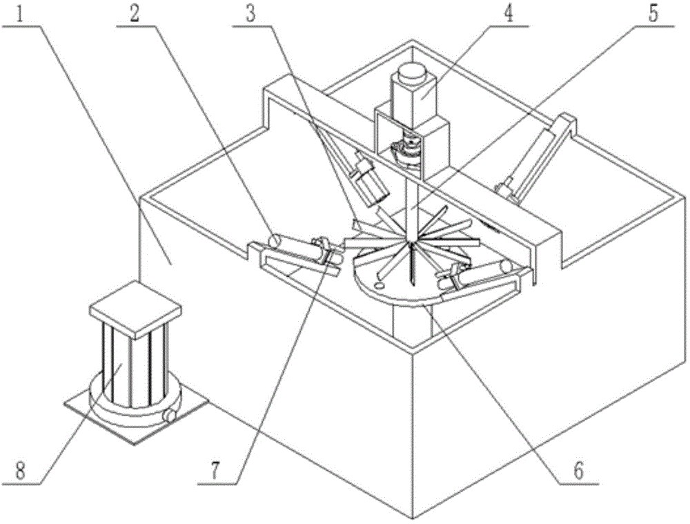
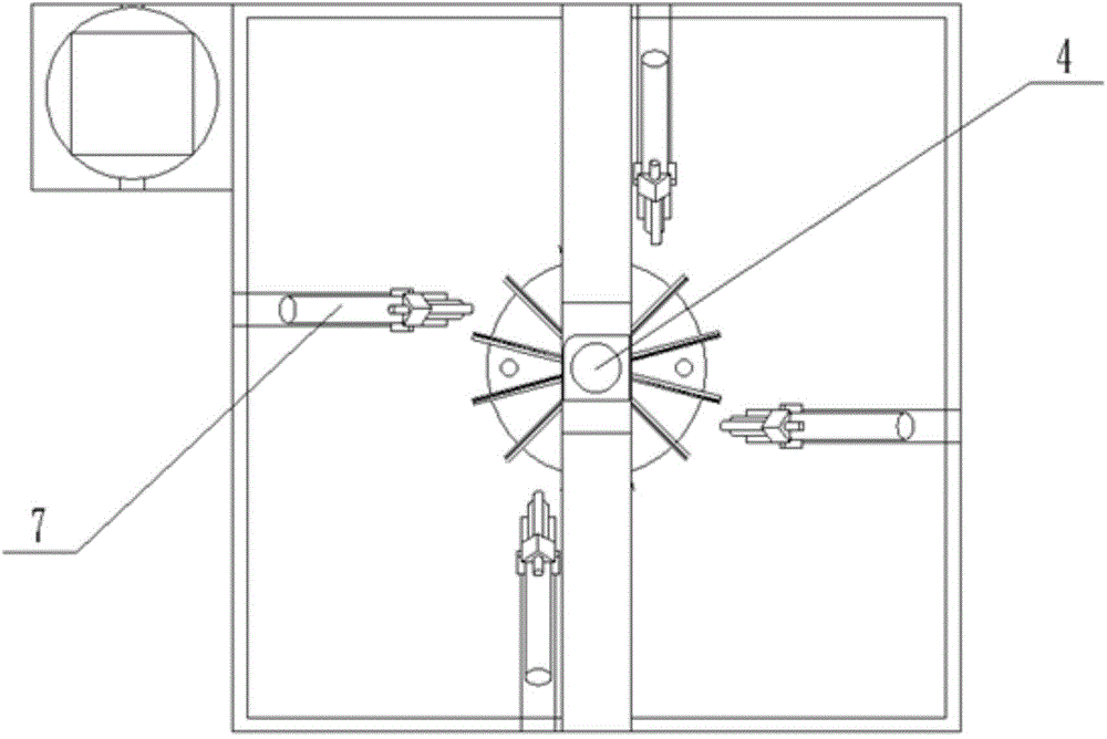
[0019] Such as figure 1 , figure 2 As shown, an ultrasonic polishing processing device using gas-liquid-solid three-phase abrasive flow, including a computer control system, abrasive flow processing pool 1, ultrasonic generator 2, pneumatic pipeline 7, high-speed blade rotating device, and workpiece installation platform 6 and an abrasive flow stirring pump 8, a crossbeam is arranged above the abrasive flow processing pool 1, a high-speed blade rotating device is fixed on the crossbeam, and a workpiece installation platform 6 is fixed directly below the high-speed blade rotating device for abrasive flow processing In the pool 1; the abrasive flow stirring pump 8 is arranged on the side of the abrasive flow processing pool 1 for stirring the abrasive flow in the abrasive flow processing pool 1; the ultrasonic generator 2 is provided with four, and the The sonotrode 2 is f...


PUM


Abstract

The invention discloses an ultrasonic polishing processing device using a gas-liquid-solid three-phase abrasive particle flow, the ultrasonic polishing processing device includes a computer control system, an abrasive particle flow processing pool, an ultrasonic generator, a pneumatic pipeline, a high speed blade rotation device, a workpiece installation platform and an abrasive particle flow mixing pump, a beam is arranged above the abrasive particle flow processing pool, the high speed blade rotation device is fixed on the beam, the workpiece installation platform is fixed in the abrasive particle flow processing pool arranged just below the high speed blade rotation device, the abrasive particle flow mixing pump is arranged on the side face of the abrasive particle flow processing pool, and is used for mixing an abrasive particle flow in the abrasive particle flow processing pool, the ultrasonic generator is fixed on the side face of the abrasive particle flow processing pool, and an emission head is directly faced to the workpiece installation platform. The ultrasonic polishing processing device can be used for real-time acquisition of temperature and viscosity signals for feedback regulation of ultrasonic bubble generator power so as to ensure processing stability; and the ultrasonic bubble generator is cooperated with airflow, and circumferentially arranged, can better improve the uniformity of the number of the workpiece surface bubbles, and improves the processing efficiency.

Description

technical field [0001] The invention relates to the technical field of ultra-smooth surface polishing processing equipment, and more specifically, relates to an ultrasonic polishing processing device utilizing gas-liquid-solid three-phase abrasive particle flow. Background technique [0002] Gas-liquid-solid three-phase abrasive flow ultrasonic machining refers to the addition of ultrasonic bubble generator drive on the basis of two-phase abrasive flow, supergenetic cavitation generates cavitation bubbles, and uses bubble collapse to drive abrasive particle groups, improving abrasive flow. processing efficiency. The method greatly improves the processing efficiency of fluid abrasive particles, and the processing time can be greatly shortened. Supergenetic cavitation technology is very common in current applications. Supergenetic cavitation means that the tiny bubble nuclei in the liquid are activated under the action of ultrasonic waves. With the growth and contraction of t...

Claims


Application Information

Patent Timeline
IPC IPC(8): B24C3/02B24C9/00B24C5/06B24C7/00
CPCB24C3/02B24C5/06B24C5/062B24C7/0007B24C9/00
Inventor 计时鸣葛江勤谭云峰金明生赵军
Owner ZHEJIANG UNIV OF TECH
Learn More