Storage tank gas phase communication device
A gas-phase communication and interconnection technology, applied in the field of gas-phase communication devices of storage tanks, can solve the problems of low oil and gas recovery efficiency, gas-phase explosion risk, etc., and achieve the effects of reducing the generation of excess gas, improving efficiency and life, and achieving good technical effects.
- Summary
- Abstract
- Description
- Claims
- Application Information
AI Technical Summary
Problems solved by technology
Method used
Image
Examples
Embodiment 1
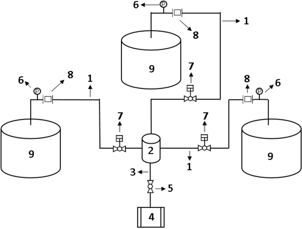
[0018] like figure 1 A storage tank gas-phase communication device shown involves three storage tanks, including three gas-phase communication pipelines 1, oil gas adsorption and desorption tank 2, oil gas recovery pipeline 3, oil gas recovery device 4, control valve 5, pressure gauge 6, Emergency cut-off valve 7, flame arrester 8, storage tank 9.
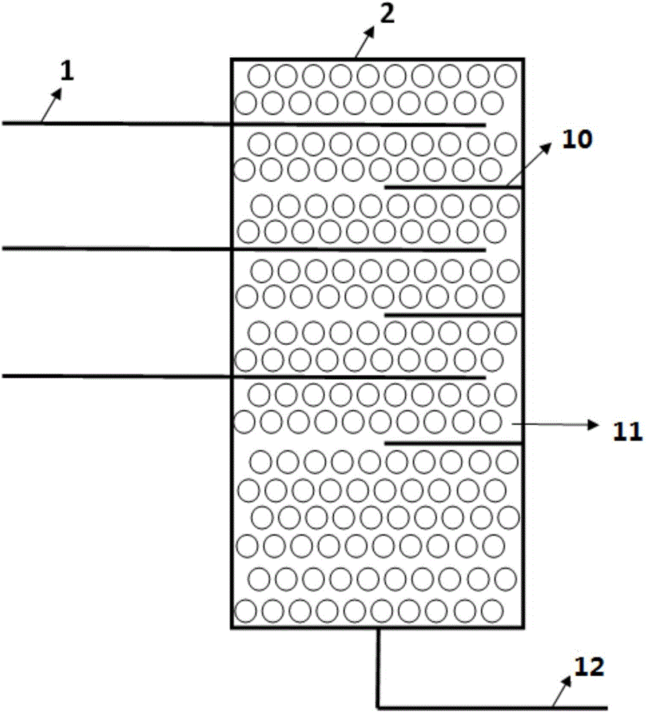
[0019] The oil and gas adsorption and desorption material filled in the oil and gas adsorption and desorption tank 2 is nonflammable, the oil and gas adsorption and desorption material 11 is hydrophobic silica gel, and the material of the baffle 10 is 304 stainless steel. Oil and gas adsorption and desorption tank 2 is provided with an oil and gas recovery pipeline at the bottom, and the oil and gas recovery pipeline is connected with the oil and gas recovery device. The ratio of the length of the gas-phase communication pipeline 1 in the adsorption and desorption tank 2 to the diameter of the oil-gas adsorption and desorption tan...
Embodiment 2
[0027] According to the conditions described in Embodiment 1, a storage tank gas phase communication device involves two storage tanks, including two gas phase communication pipelines 1 and two baffles 10 . The length of the gas-phase connecting pipeline 1 located in the oil-gas adsorption and desorption tank 2 has a diameter ratio of 0.6:1 to the oil-gas adsorption and desorption tank 2, and the length of the baffle 10 and the oil-gas adsorption and desorption tank 1 have a diameter ratio of 0.7: 1. The distance between the baffle plate 10 and the gas-phase communication pipeline 1 immediately above the baffle plate 10 is 15% of the filling height of the oil and gas adsorption and desorption material 11 .
[0028] The oil and gas adsorption and desorption material 11 is zeolite molecular sieve, and the material of the baffle plate 10 is carbon steel, which is nonflammable.
Embodiment 3
[0030] According to the conditions described in Embodiment 1, a storage tank gas phase communication device involves two storage tanks, including two gas phase communication pipelines 1 and two baffles 10 . The length of the gas-phase communication pipeline 1 located in the oil-gas adsorption and desorption tank 2 is 0.7:1 to the diameter ratio of the oil-gas adsorption and desorption tank 2, and the length of the baffle plate 10 is 0.8 to the diameter ratio of the oil-gas adsorption and desorption tank 1: 1. The distance between the baffle plate 10 and the gas-phase communication pipeline 1 immediately above the baffle plate 10 is 20% of the filling height of the oil and gas adsorption and desorption material 11 .
[0031] The oil and gas adsorption and desorption material 11 is alumina, and the material of the baffle 10 is phenolic plastic, which is nonflammable.
PUM
 Abstract
Description
Claims
Application Information
 - R&D
- Intellectual Property
- Life Sciences
- Materials
- Tech Scout
- Unparalleled Data Quality
- Higher Quality Content
- 60% Fewer Hallucinations
Browse by: Latest US Patents, China's latest patents, Technical Efficacy Thesaurus, Application Domain, Technology Topic, Popular Technical Reports.
© 2025 PatSnap. All rights reserved.Legal|Privacy policy|Modern Slavery Act Transparency Statement|Sitemap|About US| Contact US: help@patsnap.com


