Sewage treatment system and sewage treatment method

A technology of sewage treatment system and sewage treatment method, which is applied in the fields of water/sewage multi-stage treatment, water/sludge/sewage treatment, chemical instruments and methods, etc. and other issues to achieve the effect of improving efficiency

Active Publication Date: 2015-07-22
SHENGDA ENVIRONMENTAL ENG CO LTD
View PDF6 Cites 13 Cited by
  • Summary
  • Abstract
  • Description
  • Claims
  • Application Information

AI Technical Summary

Problems solved by technology

In the prior art, most of the chemical treatment methods are used, and the existing problems are: ①Because the dosing amount cannot be absolutely suitable, a small part of the heavy metal salt will not be flocculated or coagulated, so it is still in the form of tiny particles suspended in the wa

Method used


Image

  • Sewage treatment system and sewage treatment method
  • Sewage treatment system and sewage treatment method

Examples


Embodiment 1

[0021] Embodiment 1 sewage treatment system

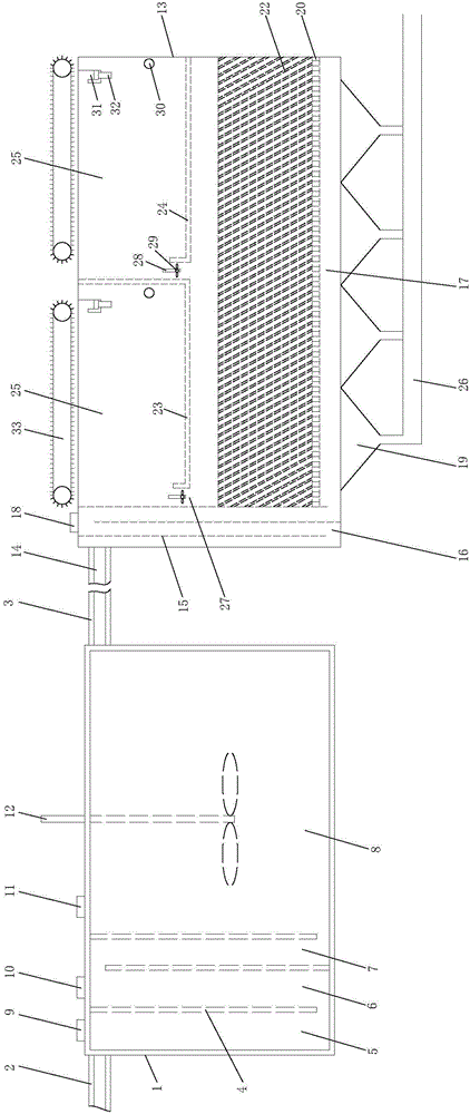
[0022] Such as figure 1 As shown, the sewage treatment system consists of a flocculation tank and a sedimentation tank.

[0023] The flocculation tank is as follows: the upper end of the tank body I (1) is provided with a sewage inlet (2) and a reaction water outlet (3), and one end of the sewage inlet (2) in the tank body I (1) is provided with 3 baffles Ⅰ(4) divides the pool body (1) into chamber Ⅰ(5), chamber Ⅱ(6), chamber Ⅲ(7) and chamber Ⅳ(8) in turn, and the upper end of chamber Ⅰ(5) is provided with a sodium hydroxide inlet (9), the upper end of chamber II (6) or chamber III (7) is provided with calcium chloride inlet (10), the upper end of chamber IV (8) is provided with aluminum chloride inlet (11), and the upper end of chamber IV (8) is provided with Stirring device (12).

[0024] Described settling tank is: the upper end of pond body II (13) is provided with reaction inlet (14), and reaction inlet inlet (14) one end i...

Embodiment 2

[0026] Embodiment 2 sewage treatment method

[0027] Adopt the sewage treatment system of embodiment 1, method is as follows:

[0028] 1. Flocculation treatment: The sewage enters the flocculation tank through the sewage inlet (2), enters the chamber IV (8) through the chamber I (5), chamber II (6) and chamber III (7) in turn, and enters the chamber IV (8) through the sodium hydroxide inlet (9 ) is fed into sodium hydroxide to adjust the pH to be 8-9, and the calcium chloride aqueous solution that is 20% by weight is fed into through the calcium chloride inlet (10) to produce foam, and in the chamber IV (8), through the aluminum chloride The inlet (11) is fed with 10% aluminum chloride aqueous solution by weight, stirred to produce a large amount of flocculent matter, and the reaction water containing the flocculent matter is sent into the sedimentation tank through the reaction water outlet (3).

[0029] 2. Sedimentation treatment: The reaction water containing flocculated s...


PUM


Abstract

The invention creatively relates to a sewage treatment system and a sewage treatment method. According to the adopted technical scheme, the sewage treatment system is composed of a flocculation tank and a sedimentation tank. According to the flocculation tank, a sewage inlet and a reaction water outlet are formed in a tank body I, and three baffle plates I are arranged in the tank body I to sequentially divide the interior of the tank body I into a cavity I, a cavity II, a cavity III and a cavity IV. According to the sedimentation tank, a reaction water inlet is formed in a tank body II, and three baffle plates II are arranged in the tank body II to divide the interior of the tank body II into a baffling area and a sedimentation area; a polyacrylamide inlet is formed in the baffling area, a sludge hopper is arranged at the lower end of the sedimentation area, a sludge discharging pipe is arranged at the lower end of the sludge hopper, a water distribution plate with a great number of water distribution holes is mounted at the upper end of the sludge hopper, a plurality of inclined plates are mounted on the water distribution plate, and a water drainage outlet is formed in the tank body II. According to the sewage treatment system and the sewage treatment method, the principle of sedimentation and air floatation is adopted, the efficiency of solid-liquid separation is improved to the greatest extent, and the final quality of drained water which is treated is guaranteed.

Description

technical field [0001] The invention belongs to the field of sewage treatment, and in particular relates to a sewage treatment system and treatment method. Background technique [0002] In the mechanical processing industry, especially in the process of surface treatment, a large amount of industrial wastewater will be generated. If these industrial wastewater is not treated in time, it will cause serious pollution to the environment. In the prior art, most of the chemical treatment methods are used, and the existing problems are: ①Because the dosing amount cannot be absolutely suitable, a small part of the heavy metal salt will not be flocculated or coagulated, so it is still in the form of tiny particles suspended in the water , it is difficult to overcome the buoyancy of water and settle down. ② Although some metal salts are flocculated or coagulated, the particles are small, the specific gravity difference relative to water is small, and the speed of downward precipitat...

Claims


Application Information

Patent Timeline
IPC IPC(8): C02F9/04
Inventor 陈迎新张燕燕崔铎孙博君
Owner SHENGDA ENVIRONMENTAL ENG CO LTD
Why Eureka
Try Eureka