Heavy hammer type slow descent chute for conveying concrete

A heavy hammer type, concrete technology, applied in the direction of construction, infrastructure engineering, etc., can solve the problems of large damage to the chute body, relatively large impact on the conveying capacity, and affect the conveying capacity, so as to achieve good economic and social benefits and increase Concrete conveying capacity and the effect of avoiding logistics damage

Active Publication Date: 2015-07-22
SINOHYDRO BUREAU 9
View PDF9 Cites 2 Cited by
  • Summary
  • Abstract
  • Description
  • Claims
  • Application Information

AI Technical Summary

Problems solved by technology

[0005] (1) It is necessary to turn on the electric small winch to adjust the angle of the chute for each transportation, which cannot realize continuous and uninterrupted transportation, and the transportation capacity is greatly affected;
[0006] (2) The chute is lifted and lowered with a wire rope, and the structural stability is poor, and it is prone to shaking during the lifting and lowering process, which seriously affects the conveying capacity and has a large safety hazard;
[0007] (3) Although the S-shaped chute can reduce the running speed of coal in the chute, it is easy to cause damage to the coal. The greater the angle of the chute, the more serious the damage, and the reduction of its running speed by the impact of coal on the chute will cause greater damage to the chute body. Moreover, the process of coal impacting the tank body will also produce large vibrations, which is not good for structural stability.
[0011] (1) The buffer structure of the middle chute section above can play a certain role in buffering and dissipating energy, but it can only dissipate energy at the bottom of the logistics, and cannot play a role in buffering and dissipating large coal blocks on the face, which are still in the air. Falling freely under the action of gravity, with the continuous extension of the chute, the speed is getting higher and higher, and the impact damage to the chute is becoming more and more serious;
[0012] (2) The ring hammer set in the lower chute section is only for buffering and dissipating energy for large coal blocks. Due to the huge impact force, the ring hammer will seriously damage the coal block, and the length of the ring hammer is only 2 / 3 of the section of the lower chute section. The buffering and energy dissipation effect of the coal flow is not obvious, and the ring hammer structure is a rigid structure, which will affect the flow section and cause blockage after being extended;
[0013] (3) The above-mentioned buffer ring hammer is only suitable for the transportation of unbonded materials, and cannot be used in concrete transportation, because the quality of concrete transportation is high, and the workability of concrete (cohesion, fluidity, water retention) must be ensured.
Aggregate separation and aggregate secondary crushing will seriously affect the quality of concrete;
[0014] (4) The above-mentioned lower chute section is a fully enclosed structure, and the ring hammer is welded under the top mother plate, which makes it difficult to maintain and repair during operation, and it is impossible to adjust the ring hammer according to different slopes and different materials
[0015] To sum up, each of the existing technologies has its own advantages and disadvantages, but none of the existing technologies can better guarantee the quality of concrete delivery, and there are problems of aggregate separation and secondary crushing of aggregates, and it is difficult to control the running speed of materials.

Method used


Image

  • Heavy hammer type slow descent chute for conveying concrete
  • Heavy hammer type slow descent chute for conveying concrete
  • Heavy hammer type slow descent chute for conveying concrete

Examples


Embodiment Construction

[0041] The technical solution of the present invention is further described below in conjunction with the accompanying drawings, but the scope of protection is not limited to the description.

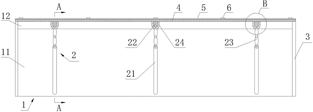
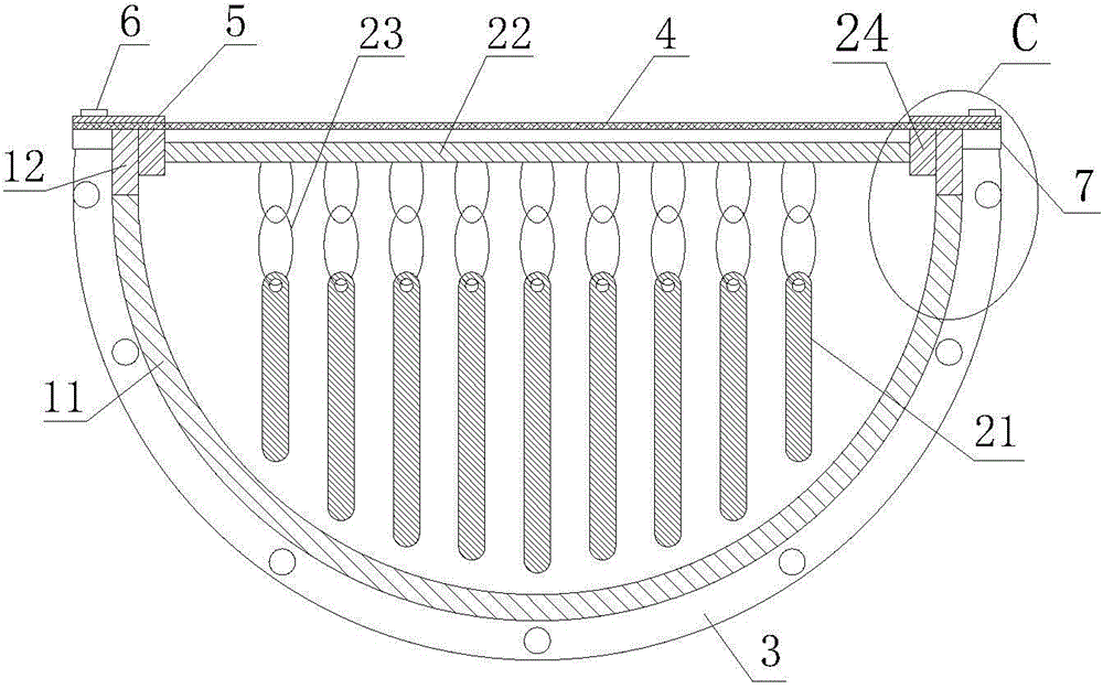
[0042] Such as Figure 1 to Figure 4 As shown, a heavy hammer type slow-falling chute for conveying concrete according to the present invention includes a chute body 1, and the chute body 1 is composed of a semicircular steel pipe 11 and a vertical shaft arranged on the opening of the semicircular steel pipe 11. Section 12, the chute body 1 is also provided with a number of buffer devices 2, wherein the buffer device 2 includes a weight 21, a cross bar 22 and a connecting part 23, and the two ends of the cross bar 22 are respectively installed on the chute body 1 On the vertical sections 12 on both sides, the weights 21 are evenly arranged on the cross bars 22 through the connecting parts 23 . The vertical section 12 is used to increase the flow section of the chute and facilitate the ...


PUM


Abstract

The invention discloses a heavy hammer type slow descent chute for conveying concrete. The heavy hammer type slow descent chute for conveying the concrete comprises a chute body which is composed of a semicircular steel tube and a perpendicular section which is arranged on an opening of the semicircular steel tube, and the chute body is further internally provided with multiple damping devices, wherein each damping device comprises heavy hammers, a cross bar and connection parts, U-shaped necks are formed in the inner wall of the perpendicular section, the two ends of cross bars are installed in the U-shaped necks respectively, the heavy hammers are evenly arranged on the corresponding cross bars through the connection parts, the top end of the chute body is covered with a rubber cover plate, the two sides of the rubber cover plate are fixed on the opening of the chute body through rubber cover depression bars, and chute lugs are arranged on the outer side of the perpendicular section of the chute body and used for fixing and connecting the rubber cover plate at the top end. According to the heavy hammer type slow descent chute for conveying the concrete, the conveying quality of the concrete is guaranteed in the concrete conveying process, the phenomena of aggregate separation, aggregate secondary crushing, chute blocking and the like are avoided, and meanwhile the conveying intensity of the concrete can be guaranteed.

Description

technical field [0001] The invention belongs to the technical field of water conservancy and hydropower engineering, and in particular relates to a heavy-hammer type slow-falling chute for conveying concrete. Background technique [0002] With the development of China's water conservancy and hydropower projects, more and more dam-building projects are being built in deep canyons, high and steep slopes and other steep terrains. The solution of concrete storage in such projects has always been an unresolved problem. According to previous engineering experience, the concrete storage methods under the conditions of deep canyons and high steep slopes mainly include portal cranes, cable cranes, vacuum slide pipes, negative pressure slide pipes, box-type full pipes, and slow-down slide pipes. Warehousing, etc. Although door machine, cable machine, vacuum chute, negative pressure chute, box-type full pipe, slow down chute and other storage methods can solve the problem of concrete ...

Claims


Application Information

Patent Timeline
Patent Type & Authority Applications(China)
IPC IPC(8): E02D15/02
CPCE02D15/02
Inventor 张正威汪庆国邹宾田志勇张永飞杨潇
Owner SINOHYDRO BUREAU 9
Why Eureka
Try Eureka