Steel pipe column concrete pumping and jacking forming matching system

A technology for concrete pumps and steel pipe columns, which is applied in the direction of columns, pier columns, pillars, etc., can solve the problems that the design value of concrete strength cannot be guaranteed, the common problems of concrete not dense and quality, and the use of space for high-altitude work is small, and the application effect is remarkable. Reasonable layout design and the effect of improving construction efficiency

Inactive Publication Date: 2015-07-22
TIANJIN NO 2 CONSTR ENG
View PDF5 Cites 1 Cited by
  • Summary
  • Abstract
  • Description
  • Claims
  • Application Information

AI Technical Summary

Problems solved by technology

[0003] Traditional steel pipe column concrete core filling technology usually adopts the high-throwing method. From the perspective of the existing construction method itself, the construction will occupy a large area of ​​the construction site, and a large number of workers must be invested in the construction; when the construction period is tight, multiple types of work are required When interspersed with work, it will be relatively difficult; traditional construction often involves high-altitude operations, which inevitably poses safety hazards during construction; when pouring concrete, the use of high-throw methods will also cause the quality of concrete to be not compact , the strength design value of concrete will not be guaranteed
In the high-altitude construction, due to the high-altitude operation and the small space used for high-altitude work, it is destined to be unstable in controllability and often waste a lot of concrete; at the same time, the construction time will be greatly extended, and the construction period cannot be guaranteed.

Method used


Image

  • Steel pipe column concrete pumping and jacking forming matching system
  • Steel pipe column concrete pumping and jacking forming matching system
  • Steel pipe column concrete pumping and jacking forming matching system

Examples


Embodiment Construction

[0015] Below in conjunction with the accompanying drawings and preferred embodiments, the specific implementation, structure and features provided by the present invention are described in detail as follows:

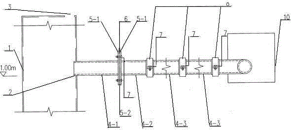
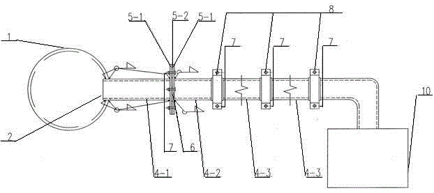
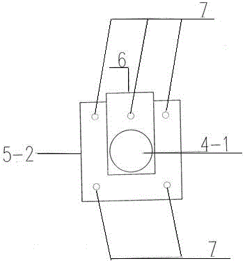
[0016] Such as Figure 1-Figure 4 As shown, a steel pipe column concrete pumping jacking forming supporting system includes a steel pipe column 1, high-pressure pump pipes 4-1, 4-2, 4-3, attached plates 5-1, 5-2, and a stop valve 6. High-strength bolts 7, flange clamps 8 and vehicle-mounted ground pump 10; wherein high-pressure pump pipes 4-1, 4-2, stop valve 6, attached plates 5-1, 5-2 and high-strength bolts 7 form a movable throat assembly.

[0017] One side of the steel pipe column 1 is provided with an opening pressure injection port 2, and the top of the steel pipe column 1 is provided with an air outlet 3; Attached plates 5-1, 5-2 are fixedly connected respectively, and pass through the stop valve 6 placed between the two attached plates 5-1, 5-1 and another atta...


PUM


Abstract

The invention relates to a steel pipe column concrete pumping and jacking forming matching system. The system comprises a steel pipe column, high-pressure pump pipes, auxiliary plates, a stop valve, high-strength bolts, flange clips and a vehicle-mounted ground pump. Pipe orifices of the two high-pressure pump pipes are fixedly connected with the two corresponding auxiliary plates respectively and are assembled through the stop valve arranged between two auxiliary plates and the other auxiliary plate corresponding to the stop valve, and the three auxiliary plates are fixedly connected through the high-strength bolts to form a movable throat assembly. An open pressure injection opening and an air outlet are formed in the steel pipe column, and the steel pipe column and the high-pressure pump pipe at one end of the movable throat assembly are welded on the open pressure injection opening to form an inputting opening; the high-pressure pump pipe at the other end of the movable throat assembly is communicated with the high-pressure pump pipe of the vehicle-mounted ground pump through the flange clips and the high-strength bolts to form an overall conveying pipeline. The construction space occupied by the system is obviously reduced, and resistance in various aspects is reduced in multi-work-type intersecting construction. The matching system is simple in structure, remarkable in effect, reusable and easy to assemble and disassemble.

Description

Technical field [0001] The present invention involves a concrete construction supporting system, which specializes in a steel pillar column concrete pumping top -up supporting system. Background technique [0002] At present, in the field of construction engineering, scientific and technological innovation and improvement of production efficiency are important means to ensure survival in a fierce competitive environment.Under the premise of ensuring the quality of construction, through scientific management and scientific and technological progress, the production method is changed to improve production efficiency and improve the competitiveness of enterprises. [0003] Traditional steel pillar column concrete irrigation technology usually uses high -throwing construction. From the perspective of the existing construction method itself, a large area of construction site must be occupied during construction, and a large number of workers need to be invested to cooperate with const...

Claims


Application Information

Patent Timeline
Patent Type & Authority Applications(China)
IPC IPC(8): E04G21/02E04C3/34
Inventor 王永朱立峰马金奎路占杰刘家森
Owner TIANJIN NO 2 CONSTR ENG
Why Eureka
Try Eureka