Tunnel blasting method

A technology of tunneling and cutting holes, which is applied in blasting and other directions, and can solve the problems of large explosion disturbance of tunnel surrounding rock, reducing the integrity of tunnel surrounding rock, affecting the contour surface of blasting excavation, etc., so as to avoid the risk of gas accumulation and facilitate popularization Use, improve the effect of the blasting effect

Inactive Publication Date: 2015-07-22
XIAN UNIV OF SCI & TECH
View PDF3 Cites 6 Cited by
  • Summary
  • Abstract
  • Description
  • Claims
  • Application Information

AI Technical Summary

Problems solved by technology

However, as the excavation depth continues to deepen, the geological conditions encountered are also complex and diverse. When the smooth blasting method is used for excavation in mountain rock tunnels, the conventional detonation sequence (cutting hole first, then caving hole, and finally At the same time as the blasting is carried out, the surrounding rock of the tunnel is more and more disturbed by the explosion, which destroys the integrity of the surrounding rock, and it is easy to cause instab

Method used


Image

  • Tunnel blasting method
  • Tunnel blasting method
  • Tunnel blasting method

Examples


Embodiment 1

[0032] Such as figure 1 with image 3 A tunnel blasting method shown comprises the following steps:

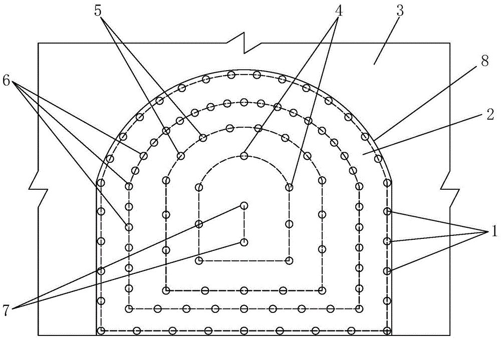
[0033] Step 1. Laying blastholes: laying a circle of peripheral holes 1 on the tunnel blasting face 2 and close to the tunnel excavation contour line 8, and laying a circle of two holes on the tunnel blasting face 2 and inside the peripheral holes 1. Ring eye 6, on the tunnel blasting face 2 and on the inside of the second ring eye 6, a caving eye 5 is arranged, and on the tunnel blasting face 2 and on the inner side of the caving eye 5, a cutting eye 4 is arranged;

[0034] In this embodiment, when laying blastholes, a drilling jumbo is used to lay out peripheral holes 1 , cutting holes 4 , caving holes 5 and secondary ring holes 6 on the blasting face 2 of the tunnel. Design the spacing of peripheral eye 1, caving eye 5 and cutout eye 4 according to the smooth blasting method. The distance between the two eyelets 6 refers to the peripheral eye 1 or the avalanche eye 5 and...

Embodiment 2

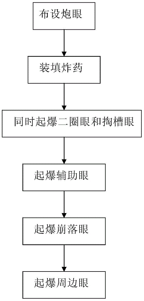
[0047] Such as figure 2As shown, the difference between this embodiment and Embodiment 1 lies in the sequence of detonation in step 3. In this embodiment, the sequence of detonation in step 3 is: first detonate the second ring eye 6 and the cutout 4 at the same time, and then detonate in sequence Avalanche eye 5 and peripheral eye 1. By detonating the second ring hole 6 and the cut hole 4 at the same time, the inter-eye penetration crack formed by the second ring hole 6 in an instant can effectively block the blast stress wave transmitted by the blasting of the cut hole 4, and at the same time, it can shorten the blasting time of all blast holes. Blasting time to avoid the risk of gas accumulation caused by too long blasting time.


PUM


Abstract

The invention discloses a tunnel blasting method. The method comprises the steps of arranging a circle of periphery holes at the positions, close to a tunnel excavation outline, on a tunnel blasting working surface, arranging a circle of secondary-circle holes at the positions, on the inner sides of the periphery holes, on the tunnel blasting working surface, arranging spallation holes at the positions, on the inner sides of the secondary-circle holes, on the tunnel blasting working surface, and arranging breaking-in holes at the positions, on the inner sides of the spallation holes, on the tunnel blasting working surface; filling explosives, wherein the periphery holes, the breaking-in holes, the spallation holes and the secondary-circle holes are filled with explosives; detonation, wherein the secondary-circle holes, the breaking-in holes, the spallation holes and the periphery holes are detonated in sequence, or the secondary-circle holes and the breaking-in holes are detonated firstly at the same time and then the spallation holes and the periphery holes are detonated in sequence. By the adoption of the method, tunnel surrounding rock can be effectively protected, the influence of blasting disturbance on the surrounding rock is reduced, crack formation on the tunnel surrounding rock is reduced, and the completeness of the tunnel surrounding rock can be well maintained.

Description

technical field [0001] The invention belongs to the technical field of tunnel blasting, and in particular relates to a tunnel blasting method. Background technique [0002] At present, the most economical excavation method in rock tunnel excavation is the blasting method. With the development of the times, the blasting method is also being improved, such as smooth blasting and pre-splitting blasting, which are widely used. However, as the excavation depth continues to deepen, the geological conditions encountered are also complex and diverse. When the smooth blasting method is used for excavation in mountain rock tunnels, the conventional detonation sequence (cutting hole first, then caving hole, and finally At the same time as the blasting is carried out, the surrounding rock of the tunnel is more and more disturbed by the explosion, which destroys the integrity of the surrounding rock, and it is easy to cause instability of the surrounding rock in geological areas with poo...

Claims


Application Information

Patent Timeline
IPC IPC(8): F42D1/00F42D3/04
Inventor 代俊潘艳宾师百垒王倩孙晓蒙杜文平
Owner XIAN UNIV OF SCI & TECH
Why Eureka
Try Eureka